 |
Save the Required Data into the New
Directories Structure
-
Save the provided data in the appropriate directories:
 |
- After the save operation of files in the corresponding
directory, it can be necessary to check that the above saved
CATPart is pointing to the saved catalog. To ensure that new
path of the feature is taken into account you need to
perform the following steps,
|
-
Open the
Pkt_udf_Knowledge_Pattern.CATPart file.
Create the NbInstances Parameter
This parameter will enable you to determine the number of
User Features you want to instantiate
-
Click the Formula icon ( ).
The Formula editor opens. ).
The Formula editor opens.
-
In the New parameter of type combo box, select
Integer and click New parameter of type.
-
In the Edit name or value of the current parameter
field, double-click Integer.1 and enter NbInstances. Click OK.
The NbInstances parameter is created.
Create the Knowledge Pattern
This feature will enable you to instantiate the User
Features
-
From the Start>Knowledgeware menu, select the
Product Knowledge Template workbench.
-
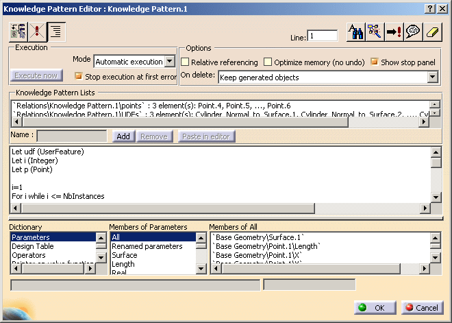
Click the Create a Knowledge Pattern icon ( ).
The Knowledge Pattern Editor opens. ).
The Knowledge Pattern Editor opens.
-
Click Add. List.1 = 0 elements is displayed in
the Knowledge Pattern Lists field. This list will list the number of
instantiated User Features. (See the image Below)
-
Click it and replace it with Boxes in the Name
field.
-
In the Mode combo box, select Automatic
execution (before root update). This way, when you change the
number of desired instantiated User Features, the script will be launched
automatically.

-
Enter the following code in the editor or copy/paste the
code contained in this
file:
Let udf (UserFeature)

					Let i (Integer)

					Let p (Point)


					i=1

					For i while i <= NbInstances

					{

					p= CreateOrModifyDatum("Point",`Instantiated Geometry`
					,`Relations\Knowledge Pattern.1\points` ,i)


					p=pointoncurveRatio(`Base Geometry\Line.1` ,`Base
					Geometry\Point.1` ,i/(NbInstances +1),False)


					udf =
					CreateOrModifyTemplate("Knowledge_Pattern_Catalog|Cylinder_Normal_to_Surface",`Instantiated


					Geometry` ,`Relations\Knowledge Pattern.1\UDFs` ,i)


					udf > SetAttributeObject("Point.1",p)


					udf > SetAttributeObject("Surface.1",`Base
					Geometry\Surface.1` )


					EndModifyTemplate(udf)


					}
|
 |
While writing this code,
you can select object from the specification tree or from
dictionary of members to add it in the script. |
 |
The script above can be
explained as follows,
- You first declare the three variables and set the
value to the integer variable.
						Let udf (UserFeature)

						Let i (Integer)

						Let p (Point)

						i=1

					For i while i <= NbInstances
- One of the attribute required by the UDF is point,
so the first step is to build an explicit point(p).
Using the member CreateOrModifyDatum from Generative
Function dictionary you can creates equally spaced
points along the length of the line.
p= CreateOrModifyDatum("Point",`Instantiated
						Geometry` ,`Relations\Knowledge Pattern.1\Points` ,i)
Inputs required,
- Object Type - 'Point'
- Location in Specification tree - 'Instantiated
Geometry' Geometrical Set
- Knowledge Pattern List that should track point
geometry - 'Points' list
- Index Number within the list - its derived by
Number of Instances
- Now explicit point exists but needs to be connected
to existing geometry. using the member PointOnCurveRatio
from Point Constructor dictionary following script will
compute the distance ration between the instances.
p=pointoncurveRatio(`Base Geometry\Line.1` ,`Base
						Geometry\Point.1` ,i/(NbInstances +1),False)
Inputs Required,
- Supporting Line - Base Geometry\line.1
- Reference Geometry to which the ratio is
computed - Base Geometry\Point.1
- The ratio of distance on the curve, in this
scenario it is calculated by an equation
- The direction represented by Boolean
- Now it sets the variable udf earlier defined as
UserFeature. Using member CreateOrModifyTemplates from
Generative Functions it refers to the catalog stored in
Knowledge folder and instantiate the udf from the
catalog.
udf =
						CreateOrModifyTemplate("Knowledge_Pattern_Catalog|Cylinder_Normal_to_Surface",`Instantiated
						Geometry` ,`Relations\Knowledge Pattern.1\UDFs` ,i)
Inputs required,
- Location in Specification tree where instance to
be created - 'Instantiated
Geometry' Geometrical Set
- Knowledge Pattern List that should track udf - 'UDFs'
list
- Index Number within the list - its derived by
Number of Instances
- This lines maps the udf object to the input in which UDF is instantiated.
udf > SetAttributeObject("Point.1",p)
udf > SetAttributeObject("Surface.1",`Base
						Geometry\Surface.1` )
Inputs Required,
- Object in UDF - Point.1, Surface.1
- Object in which UDF is instantiated - P,
Surface.1
- The last line ends the instantiation process of our
variable.
EndModifyTemplate(udf)
|
-
In the specification tree, click the NbInstances
parameter. Use the spin box to indicate the number of instances you want
to instantiate (3 in this scenario.)
-
Click Execute now. The 3 cylinders are
instantiated. Click OK to close the Knowledge Pattern window.
-
Double-click twice the parameter in the specification
tree. The Edit parameter dialog box displays.
-
Use the spin box to set the number of instances to 5 and
click OK. 2 instances are added. Click
here to open the Part containing the Knowledge Pattern.
|
![]()