|
This procedure describes how to
load or insert resources to inspect
a product (e.g., a CMM) into the PPR tree.
In this procedure, two of the resources will be loaded using the
catalog browser. The resources loaded directly into the
.CATProcess document are a CMM and a probe. |
 |
The PPR tree should already have the SAMPLE PART listed
under the product node and the FIXTURE part listed under the resources
node. |

|
Each resource loaded from the catalog browser is
treated as indivisible. Although the parts that make up the
resource appear on the PPR tree, selecting any part of a resource means
that the entire resource has been selected. There are two
catalog libraries available:
- startup\INSPECTV5lib\Catalogs\DEVICES\OLD_LIB:
This library contains inspect resources originally created from
DELMIA D5 data. This library of catalogs was the original
library available to V5 users.
- startup\INSPECTV5lib\Catalogs\DEVICES: This
library contains inspect resources created within V5. It
contains more data than the original library. It includes
components such as laser trackers, and it contains two probe head
catalogs: one each for manual and motorized probe heads.
The paths for the catalog libraries are given relative to the
startup directory. The location of the startup
directory varies, depending on how you (or your system's
administrator) has installed V5.
|
 |
Using the Catalog Browser
|
|
-
On the Activity Management toolbar, click
Catalog . .
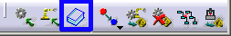 |
| The Catalog Browser window appears. |
 |
|
|
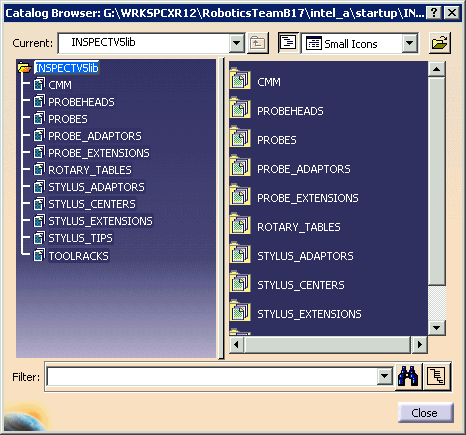
If the catalog browser appears empty or if it does not have
the INSPECTV5lib catalog available, take the following steps: |
| |
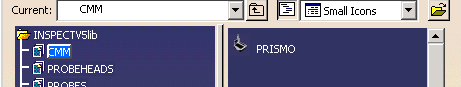
-
Select the open folder icon (banded by blue, in
the image below).
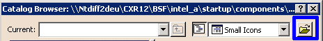 |
| A File Selection dialog box appears.
|
-
Navigate to the directory in which the
Inspect catalog appears.
| The catalog is in a subdirectory of the
startup directory. The location of the
startup directory depends on how your V5 product was
installed. Use your operating system's search function
to identify the startup directory's location.
From startup, the path is: |
- startup/INSPECTV5lib/Catalogs/DEVICES
(for catalogs with resources created in V5)
-
startup/INSPECTV5lib/Catalogs/DEVICES/OLD_LIB (for
catalogs with resources created in D5)
|
-
Select the INSPECTV5Lib.catalog file and click
Open on the File Selection window.
| The INSPECTV5lib catalog appears as in the image above. |
|
-
In the left panel, double-click CMM.
| The items in the CMM catalog appear in the right panel. |
-
Locate the PRISMO CMM using one of the methods
described below:
|
|
- Scroll through the CMM list in the right panel.
- Use the Filter
 button to locate the device.
|
| |
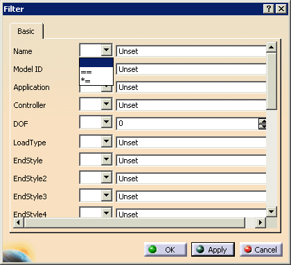
-
When you click the Filter
button, the Filter dialog box appears:
-
From the list to the right of the Name
field, select either exact match (==) or partial
match (*=).
-
In the text entry box to the right, enter either
the full name PRISMO (capitalization is important) or a portion
of the name, depending on whether you selected exact or partial
match.
-
Click OK .
| PRISMO appears in the right panel. |
 |
|
-
Click on PRISMO in the right panel.
| In the geometry area, a set of white crossed lines and the CMM
data appears. |
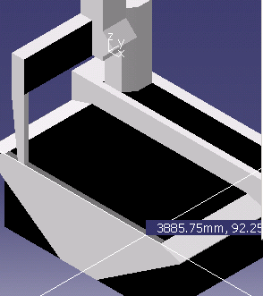 |
-
Move the CMM to a place within the geometry (final
positioning occurs after the CMM is loaded, therefore precise
placement is not necessary in this step) and click.
| The CMM is now loaded into the PPR tree under the resource
node. |
|
|
Positioning the Resources Using Snap
|
|
|
The part and its fixture are usually designed in the
same reference frame (design in context) because best practices
recommend that the CMM should be positioned relative to the part and
fixture, not vice versa. |
| |
-
Click Device Selection
 . .
| Device Selection
enables you to select an entire device, rather than discrete parts
of a device. |
-
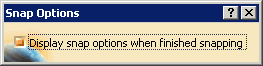
On the Layout Tools toolbar, click
Snap.
 |
| The Snap Options message appears. |
 |
-
Click on the CMM.
| The Define Reference Plane (From) dialog box
appears. |
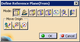 |
| The define plane mode is selected by default. |
-
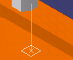
Select a point on the face of the CMM.
| A white box defines the plane; a white arrow pointing away
from the plane defines the direction of the snap. |
 |
-
Click OK.
-
Select the fixture.
| The Define Reference Plane (From) dialog box again
appears. |
-
Select a point on the bottom of the fixture.
-
Click OK.
| The Snap Options dialog box appears. |
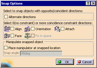 |
-
Verify that the Attach check box is not
selected.
|
|
Depending on the initial position of the fixture relative to
the CMM, select the Alternate directions check box. |
-
Click OK.
| The fixture and sample part are snapped to the top of the CMM. |
 |
-
Use Catalog
per steps 1-5 to load the probe head PH10.
|
|
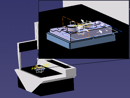
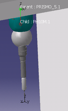
When you select the probe head (or other items loaded from the
catalog), you see a green manipulation handle that surrounds the
device. This manipulation handle enables you to move the
selected device more easily. When you move the cursor on the
manipulation handle, you see crossed white lines that also help
you visualize where an object is moving in the geometric space .
For more information, see "Using the Manipulation Handle" in the
3D Simulation for Manufacturing User's Guide. |
| |
 |
-
Use Snap to position the probe head onto the CMM using steps
6-15, with the three exceptions noted below.
to position the probe head onto the CMM using steps
6-15, with the three exceptions noted below.
- You want to snap the probe head to the CMM, so once you have
selected Snap,
select the probe head and then the CMM.
|
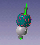
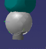
- Instead of selecting a plane on the surface of the CMM or
probe head, first position the cursor over the parts until you
see the green connector arrows (see images below), and then
click. Using the connectors means you do not see the
Define Reference Plane (From) dialog box.
You cannot see the
connectors if you are in cache mode.
(In the image of the connector on the CMM below, a view of the
part has been omitted to better show the arrow; normally the
part and fixture would be present.)
|
|
- When you get the Snap Options dialog box, select the
Attach check box.
|
|
|
You can use Jog to see the resources (e.g., the probe head) "in action" on the
CMM.
to see the resources (e.g., the probe head) "in action" on the
CMM. |
| |
With Jog,
you can select the CMM or smaller devices such as the probe head.
|
| |
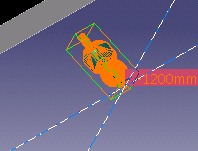
If you move the cursor over the probe head, you can see arrows
on the geometry, showing the direction of movement allowed on the
probe head. |
| |
 |
| |
Use either the compass or the dialog box to move the device. |
| |
Use the Reset button when you are finished jogging
the device. |
|
|
Loading and Positioning the Tool Sample
|
| |
-
Click on the link to the
TOOL_SAMPLE.CATProduct file.
| The TOOL_SAMPLE.CATProduct file opens in a product window. |
-
Drag and drop the TOOL_SAMPLE.CATProduct file into the
Resource List node of the process window.
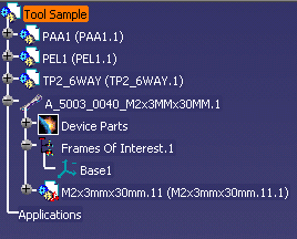 |
| Tool Sample should appear both in the geometry and in the PPR
tree. |
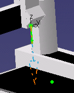
-
Use Steps 6-15 to snap the tool
sample to the probe head, with the following caveats:
- Remember that you want to snap the tool sample to the the
probe head. Once you have selected Snap,
select the tool sample and then the probe head.
- You should use the connectors in the tool sample and the
probe head for snapping. Remember that these connectors
will not be visible if you are in cache mode.
- Do not select the Attach check box in the Snap
Options dialog box.
|
 |
|
|
|
This procedure completes putting your resources in
place; you are ready to start adding activities to your inspection
process. The first inspection activity should be
defining the machine coordinate system. |