 |
The load manikin parameter corresponds to the forces
applied on the body segments. This load parameter is considered when
making calculations such as Balance IK Behavior, Center of Gravity, and
Biomechanics. This procedure describes how to
create and edit
load parameters on hands. You can also create loads on
other segments and
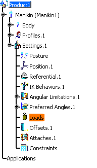
create load offsets. When a manikin is initially created, an empty Load node is
automatically created in the specification tree.
|

|
Create Load Parameters on Hands
|
| |
-
From the Manikin Tools toolbar, select the Inserts
a new load
 and in the specification tree, select the manikin.
 The
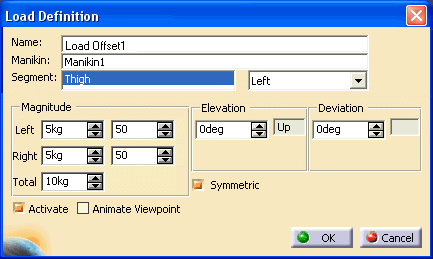
Load Properties dialog box appears.
-
Specify:
- the magnitude (force) for the the left and right hand
|
- the elevation and deviation (for carrying, pushing/pulling,
and lifting/lowering)
|
-
By default the Symmetric checkbox is active and the
specified load is applied on both hands with the same orientation. When
this checkbox is deactivated, different elevations and deviations can
be applied to the left and right hand separately.
-
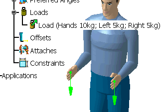
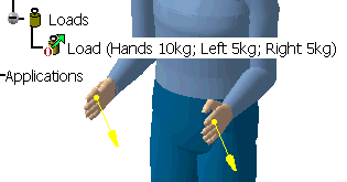
When the editing is complete, click OK. In the specification tree, a description (total, right,
and left force magnitudes) appears under the main Loads node. The load representations (forces acting on the hands)
are shown in the 3D view.
|
|
|
Edit Load Parameters
|
| |
-
To edit the current load parameters, double-click the
Load (with description) node in the specification tree. The
Load
Properties dialog box reappears.
OR
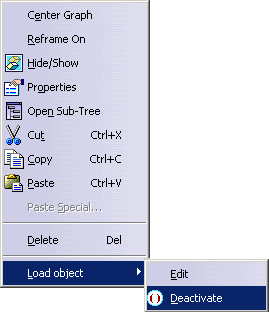
In the specification tree, right-click on the Load (with
description) node and choose Definition from the contextual menu. The
Load Properties dialog box reappears.
-
If the total magnitude is set to 0, the load is removed
from the Loads node in the specification tree.
-
Cut, Copy, and Paste options in the contextual menu are
also available for the Load node.
-
If Deactivate is chosen, the load node is deactivated
(as shown by the deactivate symbol) and the load representations in the
3D view change color.
|
| |
Display Options
|
|
The display options are located in the Tools > Options > Ergonomics Design &
Analysis > Human Builder > Display tab. |