Defining Loads on Other Segments

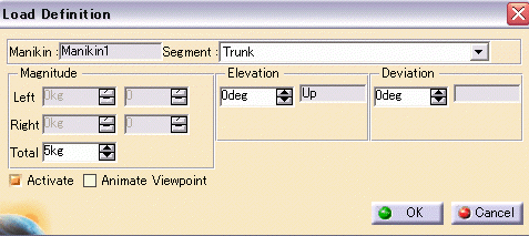
This provides a more realistic behavior of the Biomechanics Analysis by allowing the use of loads positioned on segments other then just the hands. Therefore, Biomechanics Analysis can be applied on manikin 
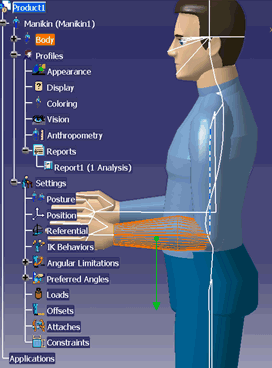
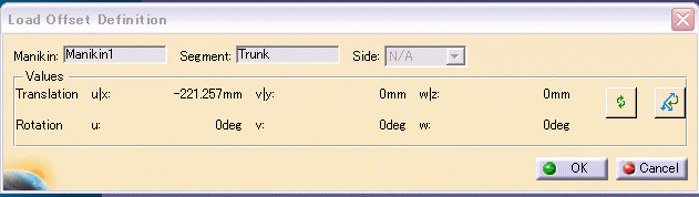
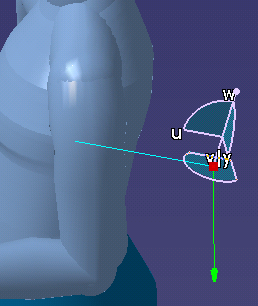
having loads on shoulders, forearms and back.

Moreover, in order to have a more accurate Biomechanics Analysis as possible with the presence of multiple loads, the notion of loads offset has been introduced.  This is particularly true for the case of load applied in parallel with the manikin's back. Most of the time there is an offset between the load and the back.

Create Load on Other Segments

 
  1. From the Manikin Tools toolbar, click Inserts a new load and in the specification tree, select the manikin.

    The Load Properties dialog box appears.


  2. Select the segment (e.g., Trunk or Arm).

    Only one load can be added to one segment. Its 3D representation is an arrow the starting end of which is located in the middle of the segment.


  3. Click OK.

    A load node for each load creation is added and visible into the tree under the Loads node.  Each individual load node displays a description including the segment to which the load is related, the total load, and the load for each side if applicable.


Create Load Offset

 
  1. Click Inserts a New Load , and add a load to a manikin segment, as described above.

  2. In the PPR tree, right-click a load item and select Load object > Define Offset...

    The Load Offset Definition dialog box appears.

  3. Move the compass to create the offset.

    As you move the compass, the values in the dialog box show the offset.

  4. Click OK.

  Just as only one load can be added to one segment at a time, only one load offset can be added to a load.

A load offset node for each load offset created is added in the PPR tree under the Loads Offset node.  Each load offset node displays a description including the name of the load offset and the name of the segment to which the load offset is related.