Creating Constraints Using Single Type of Geometry Elements
-
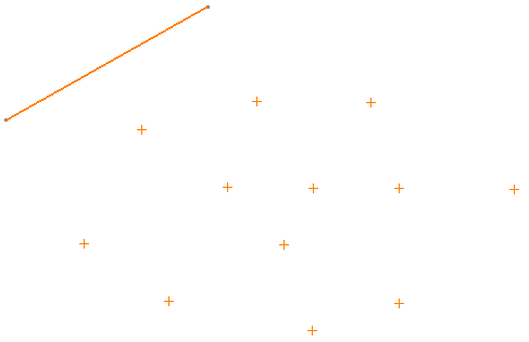
Select the points using trap selection or by pressing Ctrl.
-
Click Constraints Defined in Dialog Box
 in the Constraint toolbar.
The Constraint Definition dialog box appears. It shows available constraints considering the selected entities. These constraints are re-computed when you select the target geometry. -
Select the Target Element check box and select an element to create a constraint.

- Select the line in this case.
- When you select the Target Geometry check box, you can select the reference element. However, after selection if you clear the Target Geometry check box, the target element is removed from the selection and the constraints are shown as per current selected set of entities.
The Constraint Definition dialog box now shows selected element in the Target Element box and available constraints.
-
Select the required constraint, for example, select Coincidence and click OK.
Coincidence constraint is created between the selected points and the line (target element).
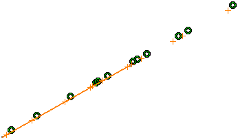
Similarly, you can create constraints between circles and the target line, or lines and the target lines, etc.
Creating Constraints Using Mixed Type of Geometry Elements
You can create same constraints between mixed type of geometry elements and a target element.
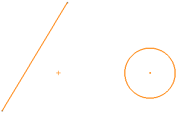
Create a line, a circle and a point.
-
Select the created geometry elements: the point, the circle and the line.
-
Click Constraints Defined in Dialog Box
in the
Constraint toolbar.
The Constraint Definition dialog box appears. It shows available constraints considering the selected entities. These constraints are re-computed when you select the target geometry. -
Select the Target Element check box and select an element to create a constraint.
Select the line in this case.
The Constraint Definition dialog box shows all the possible constraints that can be applied between each of the entity from the selected set and the selected element in the Target Element box.
In our example, the selected set contains a line, a circle and a point. The target geometry selected is a line. In this case, the following constraints are displayed:- Constraints which are possible between a point and line
- Constraints which are possible between a circle and line
- Constraints which are possible between a line and line.
-
Select Midpoint and click OK.
The point is placed at the midpoint of the line and the midpoint constraint is created.
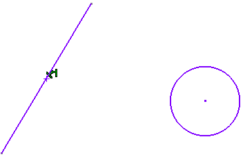
- Midpoint constraint is only applied between the point and the target line. In this case, the circle and the line from the set are ignored.
- The selected constraint type is applied to all possible pairs of the selected set entity and the target geometry. The entities where the selected constraint type cannot be applied are left unconstrained.
- When you select the Target Geometry check box, you can select the reference element. However, after selection if you clear the Target Geometry check box, the target element is removed from the selection and the constraints are shown as per current selected set of entities.