Setting Text Properties |
|
Text properties such as font style, size and justification can be applied to text, dimension text, text with leader, balloon and datum target, as well as to text included in datum features and geometrical tolerances. You can set the properties of a text either before or after creating it.
If the Text Properties toolbar is not displayed, choose View> Toolbars, and select Text Properties.
 |
-
Select the text.
")
-
Choose the properties you want to apply to this text in the Text Properties toolbar. For instance, select Italic and Bold. The properties you chose are applied to the selected text.
")
DS ISO 1 Open Type Font
DS ISO 1, an Open Type font based on the ISO 3098 standard defining text representation, is delivered along with the application to ease the exchange of standardized documents.
The DS ISO 1 font supports new engineering symbols. You can access these engineering symbols from the Engineering Symbols node in the Standard Definition dialog box.
|
|
DS ISO 1 is provided "as is". It is left up to each user/company to decide whether this font fits requirements in terms of annotation representation and compliance to ISO standards (or any other standard). |
From a general standpoint, DS ISO 1 is a variable-pitch font, designed as Open Type with True Type format outlines definition. It has been designed based on ISO 3098-5:1997, ISO 3098-3:2000 and Unicode definition (i.e. character codes are assigned in accordance with Unicode definition). In particular, characters' shape, box and dimensions are based on ISO 3098-5:1997, ISO 3098-3:2000 with lettering type CB vertical (regular) and slopped (italic).
The bold style is not defined in ISO3098. A thickness has been defined
for the Bold and Bold Italic styles, consisting in a 50% addition to
that of the regular style.
DS ISO 1 contains glyphs covering the following Unicode ranges:
- Controls and Basic Latin
- Controls and Latin 1 Supplement
- Latin Extended A
- Greek
- Cyrillic
- Enclosed
Alphanumeric
Four new standards (ISO_DS, ISO_3D_DS, JIS_DS, JIS_3D_DS) are available that use DS ISO 1 as the default font. For more information, refer to Before You Begin in the Administration Tasks chapter.
Specifying the Position and Orientation of a Text |
|
If the Position and Orientation toolbar is not displayed, choose View> Toolbars, and select Position and Orientation.
 |
-
Select the text whose position and/or orientation you want to specify.
-
Enter the required values in the Position and Orientation toolbar.
-
X: sets the horizontal position.
-
Y: sets the vertical position.
-
A: sets the orientation.
-
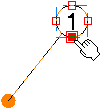
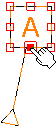
Annotation Manipulators
The following figure depicts an annotation with various manipulators:
Note: The display of manipulators for annotations can be customized based on whether the annotation is selected or its text is edited. For more information, refer to Annotation Manipulators Display.
Annotation Manipulators Display
The following table lists the default values for display of manipulators:
|
Manipulator |
Representation |
Selection |
Text Edition |
| Stretch text |
|
Displayed | Displayed |
| Resize text |
|
Displayed | Displayed |
|
Slide text |
|
Displayed | Not displayed |
| Resize leader attachment |
|
Displayed | Not displayed |
| Move leader attachment |
|
Displayed | Not displayed |
| Move leader |
|
Displayed | Not displayed |
Annotation Positioning
The attachment points are visualized when you move the pointer over the reference annotation during the annotation creation. The nearest attachment point is highlighted indicating that the annotation can be positioned on it if that point is selected. Once it is selected, the annotation is positioned on it and all the attachment points disappear.
The following types of annotations can be positioned associatively:
|
The following types of annotations can be used in associative annotation positioning:
|
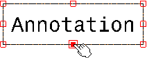
The attachment points where an associative position can be created depend on the frame type of the annotation. The following table depicts some of the frame types of annotations and their attachment points:
|
Type of Annotation |
Type of Frame |
Attachment Points |
|
| Text |
|
 |
|
|
 |
||
|
 |
||
|
 |
||
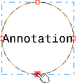
| Balloon | Circle |
 |
|
|
Datum Feature |
Square |
 |
|
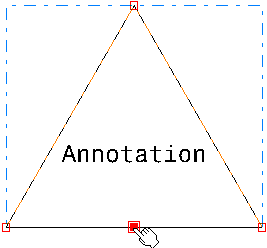
| Datum Target | Scored circle |
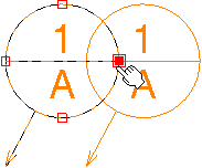 The datum target has four attachment points from the circular frame and two additional attachment points available in the datum target upper compartment and lower compartment. The attachment points of upper and lower compartment are used to attach the leader anchor point of an annotation. |
|
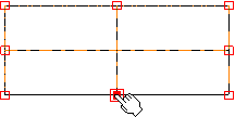
| Table | Rectangle |
 |
|
|
The attachment points for all fixed frames are on the frame even if the frame is smaller than the annotation. |
Annotation Placement on Another Annotation
Snapping of an annotation can be done during the creation of an annotation or during the creation of an associative positional link, using one of the following commands:
- Text
- Text with Leader
- Instantiate Text
- Balloon
- Datum Feature
- Datum Target
- Table
- Instantiate Table
Contextual commands:
- Positional Link > Create
- Positional Link > Replace
|
|
When positioning an annotation on an existing annotation:
|
When positioning an annotation with a leader on an existing annotation:
- The leader is removed as soon as the target annotation is selected.
- If an annotation with a leader containing an attribute link or a link template is instantiated and positioned on an existing annotation, its leader is removed but the link is resolved.
More About the Text Properties Toolbar
|
Option |
Name |
Description |
|
|
Font Name | Changes the style of the text. |
|
|
Font Size | Changes the size of the text. Note that this size cannot be inferior to 0.2 mm. |
|
|
Bold | Changes the weight of the text. Toggles between normal and heavy (bold). |
|
|
Italic | Changes the angle of the text. Toggles between normal and slanted (italic) |
|
|
Underline | Adds a line under the text. |
|
|
Strikethrough | Adds a line through the center of the text. |
|
|
Overline | Adds a line above the text. |
|
|
Superscript | Raises the text above the normal text line. |
|
|
Subscript | Lowers the text below the normal text line. |
|
|
Left Justify | Aligns multiple lines of text to the left edge of the text frame. |
|
|
Center Justify | Centers multiple lines of text within the text frame. |
|
|
Right Justify | Aligns multiple lines of text to the right edge of the text frame. |
|
|
Anchor point | Changes
the position of the point that connects the text to the drawing or to
an element. Choices are as follows:
|
|
|
||
|
|
Frame | Draws a
single-line frame around the text. A variety of different shapes is available. You can choose to create each frame with either a variable or a
fixed size. For a rectangular frame, for example, the icon
|
|
|
||
|
|
Insert Symbol |
IInsert a symbol if the selected element allows it. |
|
|

Limitations |
|
Annotations
- In the Drafting workbench, it is impossible to store annotations in a selection set.
- If you multi-select annotations and geometry and try to drag the selected elements, then either annotations or geometry will be moved (depending on what elements are located under the mouse), but not both. To bypass this limitation, you can translate the elements instead of trying to drag them.
Dimensions
In case of a dimension, the symbol inserted from the Text Properties toolbar is a prefix. You cannot have both a prefix and a suffix on a dimension. If a suffix is displayed on a dimension, creating a prefix with the Text Properties toolbar deletes the suffix from the view, and only the prefix is displayed.
![]()