The application provides a powerful command for translating elements. You may either perform a simple translation (by moving elements) or create several copies of 2D elements.
This task shows you how to translate 2D elements by using the duplicate mode and then selecting the element to be duplicated.
Translate Elements Keeping Internal/External Constraints
-
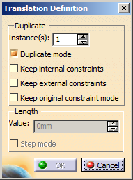
Keep the Instance(s) field to 1 and the Duplicate mode option selected.
The Duplicate mode option is selected by default, which means that the 2D elements you select will be copied. If you clear Duplicate mode, the element is moved.
-
Select Keep internal constraints.
This option specifies that you want to preserve the internal constraints applied to the selected elements in the translation. -
Clear Keep external constraints.
Any external constraint existing between the selected elements and external elements is disregarded in the translation. -
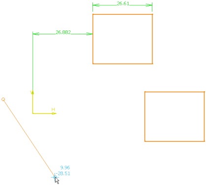
Select the elements to be translated using the trap selection.
You may either select one 2D element, or multi-select the entire 2D geometry by trapping it with the mouse as shown below.
-
Click to indicate the translation vector starting point.
You can define the translation length in the geometry area, using the mouse. For more precise results, enter a specific value for the translation length in the Translation Definition dialog box.
-
Type 30mm in the length field and press Enter.
Note: To change the step value, right-click the value field and select Change step > xxx mm. For more information about parameter management which is common to all parameters used in CATIA products, see CATIA Infrastructure User's Guide: Using Knowledgeware Capabilities: Parameters.
-
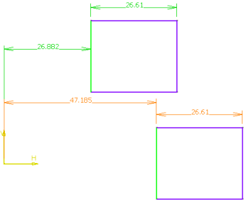
Click to indicate the translation vector ending point.
-
Click OK.
The translation is performed.
You can notice that the internal constraints are preserved in the translated element (four tangency constraints, and a parallelism constraint), whereas the external constraint (an offset constraint) is not.
Translate Elements Keeping the Original Constraints Mode
-
Click Translate
 .
.
The Translate Definition dialog box appears. -
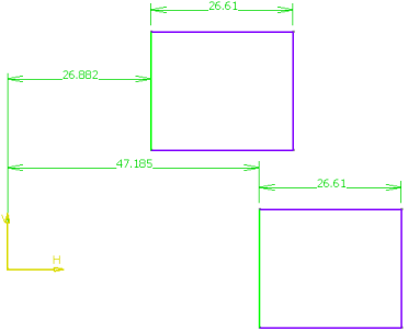
Select Duplicate mode, Keep internal constraints, Keep external constraints.
This creates a duplicate geometry retaining the internal and external constraints.
Apart from the Duplicate mode option, the Keep internal constraints, Keep external constraints, and Keep original constraints mode options are cleared, by default.
However, after you execute this command, your chosen preferences are stored and used as the default options for the next usage. -
Select Keep original constraints mode.
-
Select the rectangle using the trap selection and click to indicate translation vector starting point.
-
Click to indicate translation vector ending point.
The translation is performed. You can notice that the internal and external constraints are preserved in the translated element. -
Click anywhere in the graphic area.
The selected geometry is translated keeping the original constraints mode.
The constraints defined in the original geometry are driving constraints.
These constraints are copied to the translated geometry as is (because the Original constraints mode option is selected).If you clear the Original constraints mode option, the geometry is translated without preserving the original constraints mode (driving/driven) as shown below. 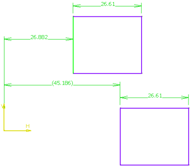
The constraints defined in the original geometry are driving constraints.
These constraints are not copied in the translated geometry (because the Original constraints mode option is cleared) which shows reference constraints.
-
The Undo
 command is available from the toolbar, while you are translating
elements.
command is available from the toolbar, while you are translating
elements. -
When translating external constraints:
-
geometrical constraints are deleted.
-
dimensional constraints are preserved but revalued.
-
More about the Translate Command
- When you are using Translation
, the top priority is to ensure the
move of geometrical elements.
This is the reason why some geometrical or dimensional constraints may be removed or modified in order to assure the move of selected geometrical elements according to the given vector of translation. - Translating elements also means re-computing distance, angle and/or
length constraint values, if needed.
Be careful: only non-fixed elements are updated. - Multi-selection is not available.