You can:
The tasks below refer to the main pulling direction, but also apply to the slider/lifter pulling direction since the dialog boxes and operating modes for those two commands are similar. More information about the parameters is available in the Pulling Direction Parameters chapter.
You must define the main pulling direction before defining the slider/lifter one.
Perform a Quick Definition
You can perform a quick definition of the pulling direction and of the mold areas.
-
Click Pulling Direction
 .
.
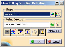
The Pulling Direction dialog box is displayed:
-
Select either one single shape by direct pick, or several elements:
- Click
 to display the selected elements.
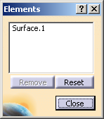
- Pick an element in the 3D viewer or the specification tree to add it to the selection.
- Select an element in the list, then click Remove to remove it from the list.
- Click Reset to reset the whole selection.
- Click Close to revert to the main dialog box.
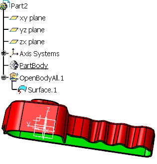
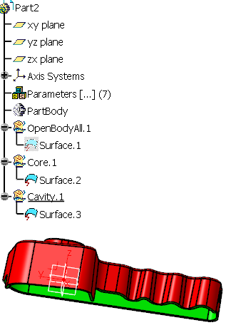
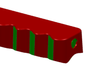
By default, the colors of the mold areas are as follows:
- Red for the Core,
- Green for the Cavity,
- Yellow for Slider/Lifter,
- Blue for Other,
- Pink for No Draft.
The pulling direction is locked as soon as a shape is selected.
By default, the pulling direction is the compass direction.The mold areas are computed and displayed.

- Click
-
If necessary, click
 to unlock the pulling
direction and modify it:
to unlock the pulling
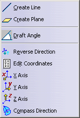
direction and modify it: - Select a line to take its orientation as the pulling direction,
- or select a plane to take its normal as the pulling direction,
- or use the Pulling Direction contextual menu:

When the direction is locked, only Draft Angle and Edit Coordinates are active. -
Define the type of output by clicking:
- either
 : the output will be only a color attribute.
- or
 : the output will
be colored extracts.
: the output will
be colored extracts.
- either
-
Click OK to validate and exit the command:
- If you have selected
, the mold areas found are colored:
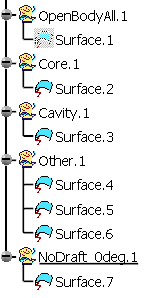
- If you have selected
, the mold areas are created as colored extracts in
the specification tree.
- If you have selected
Improve the Definition of the Mold Areas
You can improve the definition of the mold areas by using the quick dispatch icons.
-
Click
 to perform a fly analysis.
The normal of the face and the angle value between the pulling direction and this normal are displayed as you drag the cursor.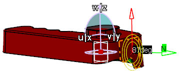
-
If the mold areas are not clearly defined, use the Dispatch Toolbar to improve the definition.
-
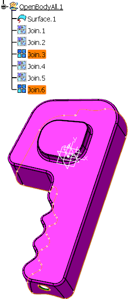
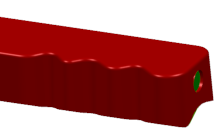
In this example, some faces are found as Other, whereas they should belong to the Core.
-
Click
 Other to Core. The blue faces are sent to
the Core.
Other to Core. The blue faces are sent to
the Core. -
If you are not satisfied, click
 to undo the last transfer.
 -
Alternatively, click
 to reset the pulling direction and start a new computation
with the robot direction.
to reset the pulling direction and start a new computation
with the robot direction.
-
-
When you are satisfied, click OK to validate and exit the dialog box.
Perform an Advanced Definition
You can access more definition options in the dialog box.
-
Click More>>.
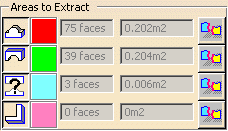
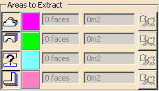
The dialog box turns to
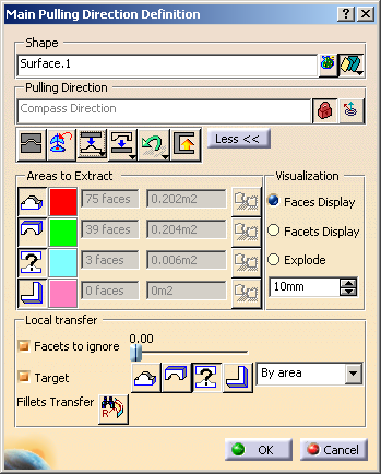
giving you information on the number of faces and surface of each mold area found. By default, all the mold area icons are pressed, i.e. active, meaning they are all taken into account in the output:
results in
-
If necessary, click a pressed icon to release it and deactivate the corresponding mold area.
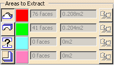
results in
-
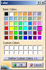
Optional: modify the color of a mold area, for example that of the Core.
Double-click the (red) color patch at the right of the mold area icon to access the color editor.
Select the required color and click OK.
-
Optional: Create the parting line by color of a given mold area.
This is possible only with
active, the output is only a color attribute.- Click
 at the end of the mold area line.
 - Click OK.
The parting line is created as a join in the active body:
- Click
-
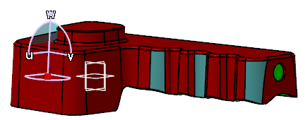
Go to Visualization to check the definition of the mold areas.
By default, the Visualization is set to Faces Display. In this example, some faces are found as Other while you expect them to belong to the Core.
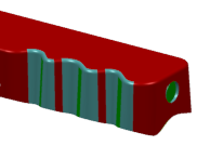
- Switch the Visualization to Facets Display.
You can see that some facets of the Other faces are seen as belonging to the Cavity. This is why the faces are seen as Other instead of Core. - Return to Faces display.
- Switch the Visualization to Facets Display.
-
Make sure the pulling direction is locked, go to Local transfer and select the Target check box.
The local transfer icons become available. -
Select the target mold area: click the Core icon
 .
.
-
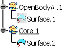
Still in No Propagation mode, pick the Other faces one by one.
They are sent to the Core.
-
When you are satisfied, click OK to validate and exit the dialog box.
![]()