These dialog boxes contain controls for:
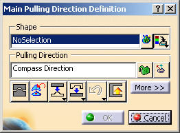
- Main Pulling Direction dialog box:
- Slider/Lifter Pulling Direction dialog box:
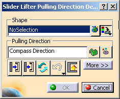
Shape
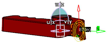
Pulling Direction
By default, it is the compass direction.
It is locked as soon as you select a surface.
-

 :
let you lock/unlock the pulling direction.
:
let you lock/unlock the pulling direction. -
 :
lets you perform a fly analysis of the faces: the normal of the face and
the angle value between the pulling direction and this normal are
displayed as you drag the cursor.
:
lets you perform a fly analysis of the faces: the normal of the face and
the angle value between the pulling direction and this normal are
displayed as you drag the cursor.
The Pulling Direction contextual menu contains the following
items:
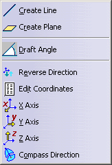
- Create Line: lets you create a line, the orientation of which will be the pulling direction.
- Create Plane: lets you create a plane, the normal of which will be the pulling direction.
- Draft Angle: lets you define the draft angle, i.e. the minimum un-molding angle between the surface and the pulling direction.
- Reverse Direction: reverses the current pulling direction.
- Edit Coordinates: lets you edit the coordinates of the pulling direction
- X Axis, Y Axis, Z Axis: sets the pulling direction to one of those axes.
- Compass Direction: sets the pulling direction to that of the compass.
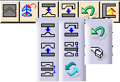
Dispatch Toolbar
- For Main Pulling Direction:
-
 :
Quick Dispatch: performs an automatic separation of the
Core and
Cavity areas.
:
Quick Dispatch: performs an automatic separation of the
Core and
Cavity areas. -
 :
Other to Core: transfers all Other faces to the
Core area.
:
Other to Core: transfers all Other faces to the
Core area. -
 :
Other to Cavity: transfers all the Other faces to the
Cavity area.
:
Other to Cavity: transfers all the Other faces to the
Cavity area. -
 :
Reduce Transitions: No Draft and Other faces are checked one by one.
When all the faces adjacent to the face that is checked are in the
same area (Core or Cavity, the checked face is transferred to that
area.
:
Reduce Transitions: No Draft and Other faces are checked one by one.
When all the faces adjacent to the face that is checked are in the
same area (Core or Cavity, the checked face is transferred to that
area. -
 :
No Draft to Other: transfers all No Draft faces to the
Other area.
:
No Draft to Other: transfers all No Draft faces to the
Other area. -
 :
Optimize Split: when small Core and Cavity areas are found in
addition to the main Core and Cavity areas, they are sent to the
Other area.
:
Optimize Split: when small Core and Cavity areas are found in
addition to the main Core and Cavity areas, they are sent to the
Other area. -
 :
Switch: switches the faces of the Core with those of the
Cavity.
:
Switch: switches the faces of the Core with those of the
Cavity.
-
- For Slider Lifter Direction:
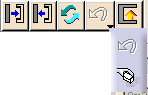
- For Both:
-
 :
undoes the last transfer.
:
undoes the last transfer. -
 :
resets the pulling direction.
:
resets the pulling direction. -
 :
Detects all the faces in undercut.
:
Detects all the faces in undercut.
Some faces are not completely visible, whether you look at them from one side of the pulling direction, or from the other. They are in undercut.
Undercut detects all those faces:- A face is not considered as hiding itself.
- For optimization purposes, faces that are pink (No Draft) at the beginning of the detection of faces in undercut are considered as "not hidden" and "not hiding". Therefore they are excluded from that detection.
- The faces in undercut take the same color as Other faces (blue).
- The remaining faces keep the color they had before starting the undercut detection.
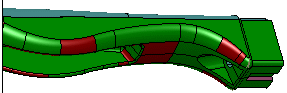
For example, the small horizontal green face below is seen as a Cavity area by a standard computation robot. But whether you see it from top or bottom, it is invisible, so it is actually a face in undercut. Applying
Undercut adds it to the Other group.
 Undercut is not applied
Undercut is applied
Undercut is not applied
Undercut is appliedThere are several ways to apply
Undercut:- either apply
Undercut just after a Quick Dispatch, when
there are no pink faces and no blue faces. In this case, all the
blue faces in the result are the faces that are at least partially
hidden.
- or send all the pink faces to the Other group, to include them in the undercut detection.
- or increase the draft angle to get more pink faces, in order to detect less faces in undercut.
- or change the color of the Other faces before
applying
Undercut in order to identify clearly the faces in
undercut (a face that belongs to Other is a face that, by
itself, is visible at least partially from both sides of the pulling
direction).
-
- The detection of faces in undercut is very precise: as soon as a face is partially hidden, even very slightly, it is detected as in undercut.
- Facets to ignore is not active for
Undercut.
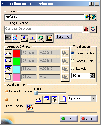
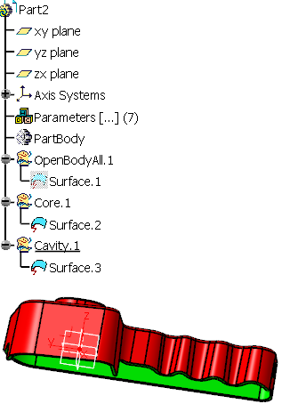
Areas to Extract
Those icons define the areas that will be extracted:
- For Main Pulling Direction:
-
 :
Core (in red),
:
Core (in red), -
 :
Cavity (in green),
:
Cavity (in green), -
 :
Other (in blue),
:
Other (in blue), -
 :
NoDraft (in pink).
:
NoDraft (in pink).
-
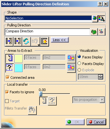
- For Slider Lifter Direction:
-
 :
Slider/Lifter (in yellow),
:
Slider/Lifter (in yellow), -
:
Other (in blue).
-
The number of their faces and their surface are given for information.
The patch of color at the right of each icon gives access to the color
editor to change the default color of the area.
![]() :
after OK, creates the parting line for the area.
:
after OK, creates the parting line for the area.
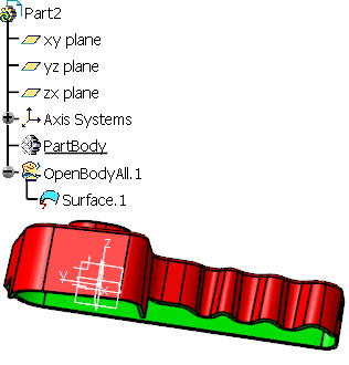
Visualization
The definition of the mold areas is based on a facettisation of the faces. The deviation of the normal to a facet with the pulling direction defines whether the facet belongs to
- the Core, the Cavity,
- or the Slider/Lifter area.
If even only one facet of a face is not clearly in one of those areas, the whole face is considered to be Other and displayed in blue. In this case, it is interesting to know how all the facets of the face behave, to decide to split the face, or to transfer it to the mold area.
- Faces display: displays the faces of the part.
- Facets Display: displays the facets on a blue face so that you can find which ones are not compatible with the rest of the face and solve the problem.
- Explode:
requires that you lock the pulling direction. Displays the graphic visualizations of
- the Core area, the Cavity area (Main Pulling Direction dialog box, Other area is ignored),
- the Slider/Lifter area and the Other area (Slider/Lifter
Pulling Direction dialog box), apart from each other, along the current pulling direction.
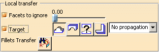
Local Transfer
- For Main Pulling Direction:
- for Slider Lifter Direction:
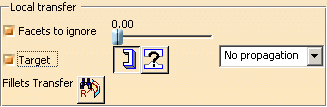
- Facets To Ignore: provides another solution to the problem of facets not belonging clearly to Core, Cavity or Slider/Lifter by ignoring a percentage of those alien faces.
- Target: requires that you lock the pulling direction, is available
in exploded view.
Lets you transfer one face of the part to one of the areas to extract (Core, Cavity, Slider/lifter, Other). - Propagation options
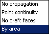
- No propagation: requires that you pick the faces you want to transfer one by one.
- Point continuity: requires that you pick one face. All the faces of the same initial color that have a point continuity with this face are selected and transferred.
- By area: useful when a few faces of a given color are found
among the destination faces, but are not connected to each other:
For example, select one red face and all the other red faces found among the green ones are transferred. The faces selected are transferred to the destination area, this transfer is taken into account immediately. - No draft faces: Transfers all the no draft faces to the target area