Within the same command, you can import:
- Only contours. The part in which you perform the import may contain no Composites Parameters.
- Zones with or without geometry.
Access to a Composites Design licence is required. - Laminates
- Rosettes
-
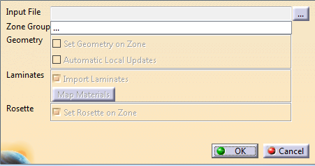
If you are importing zones in a part that contains only geometry,
define Composites Parameters and a Zones Group. Press ... to select the input file (Nastran bulk data file).
-
Click OK to import only contours.
- Contours defining PCOMP boundaries are imported.
- They are placed in an Open Body named Zones, under Composites Link.
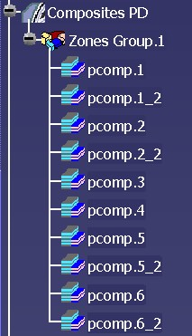
- The zone names are made from the prefix pcomp followed
by the PCOMPID.
For example, pcomp.1 refers to the contents of the PCOMP card with ID=1. - Because a CATIA zone can only be defined over one
contiguous area, if a PCOMP is used in several separate
parts of the model,
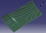
several outer contours are created around section regions.
For example, if the PCOMP region with ID=1 is used in two disconnected regions, two sets of contours are created as pcomp.1 and pcomp.1_2.
(A subscript showing the instance index is appended to the second and subsequent regions.
The order of naming is set by the lowest element ID existing in the respective regions.) - If a section region contains one or more holes, corresponding inner contours are created.
This geometry is based on the element edges and may require rework.
However, it is easier for the designer to redraw from a curve present in CATIA, rather than guessing the locations of the zones.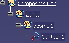
-
To import zones, select the Zone Group where the zones are imported and click OK.
Composites Link tries to map analysis materials with materials referenced in the Composites parameters, by:- Matching material names
- Matching key mechanical property values within 0.1%.
When automatic mapping is not possible, you are requested to map the materials manually.
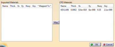
- Pick an analysis material on the left.
- Pick a Composites Design material on the right.
- Click Map.
Click OK without selecting any check box to create empty zones.
Alternatively, select the Set Geometry on Zone check box.
The contours associated with the zones are projected onto the underlying surface of the zones group.
These projections are associated with the zones.-
By default, these projections are not automatically updated.
If required, select the Automatic Local Updates check box.
Automatic Local Updates may be time consuming.
-
Select the Import Laminates check box to convert the analysis zones into a smeared equivalent description.
For every layer in the analysis PCOMP, the CATIA material is identified from the mapping.
The closest angle defined in the Composites Parameters is selected, the number in this direction is incremented accordingly. -
In the analysis input deck, check the thickness of the CATIA material given in the CATMaterial.
-
Select the Set Rosette on Zone check box to import the analysis coordinates system, if any.
If the orientation is not defined by a coordinates system, or if several coordinates systems are referenced, no rosette is set.
![]()