Composites Development Process
The general Composites development process is defined schematically
as follows: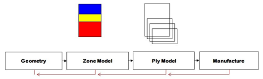
The basic geometry of a part is usually predicated by its function or
bounding constraints.
The definition of basic geometry is usually
completed by a designer using a CAD system.
Next, the zone modeling
stage begins where the structure is divided into simplified regions and a
basic Composites layup is specified.
In a zone model, material layers are not considered to extend beyond the
region of the zone.
Basic fiber directions are specified with respect to
a coordinates system, but no detail is given as to the manufacturing process
or even the order of application of material to the surface.
For
example, in a region the total layup thickness is specified as 5 mm,
with 50% of fibers in the nominal 0 direction, 10% in the +/- 45 directions,
and the remainder in the 90 direction.
This stage is usually controlled
by an analyst using a FEA system to predict structural response and to size
the zones to achieve the required performance.
At the end of this stage,
the basic Composites structure is defined but no manufacturing constraints
have been considered.
Next, the plies required to achieve the required total thickness are
specified and producibility simulations are performed.
This is the most
time-consuming part of the process as it may be found that some plies cannot
even be manufactured, so they have to be split into smaller sections or even
redesigned completely.
But this stage considers manufacturing
constraints implicitly, and allows the generation of manufacturing
information such as flat pattern shapes.
As a result, the ply model has
a good chance of being manufacturable on the shop floor without difficulty.
Finally, manufacture is completed based on the ply model.
In an
aerospace environment, laser projection systems are generally used to
project the ply boundaries onto the mold to ensure that manufacture matches
the design and analysis models.
Composites Models for Analysis and Design
During the Composites development process, designers and analysts model
the Composites structure in different ways, as summarized below.
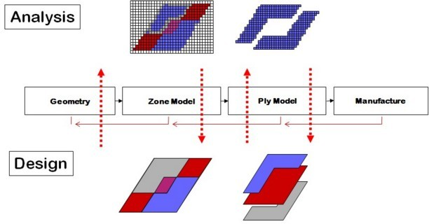
The analyst
defines zones and plies on shell finite elements, or surfaces associated
with finite elements.
The finite element model is a sufficiently detailed
abstraction of the real component for the purposes of defining the response.
The model has a very close link to the analysis code. This means that models
can be created and analyzed very quickly.
By contrast, designers define
zones and plies using geometrical surfaces and boundary curves.
This
approach is more exact but time-consuming. In general, the design model can
be sent directly to manufacture.
Comparing the two different approaches, the
analysis approach is far quicker at the expense of detail.
For example,
defining ply coverage on shell elements takes seconds per ply, whereas
defining an exact boundary curve might take orders of magnitude longer.
Where structural performance is critical and time pressure great, such as in
top-level motorsport, the ply model is generally first defined by the
analyst.
By contrast, for many aerospace components with simpler loading
conditions and developped with less time pressure, the ply model is generally
defined by the designer.
Composites Link
Composites Link allows the seamless transfer of Composites models between analysis and design as follows: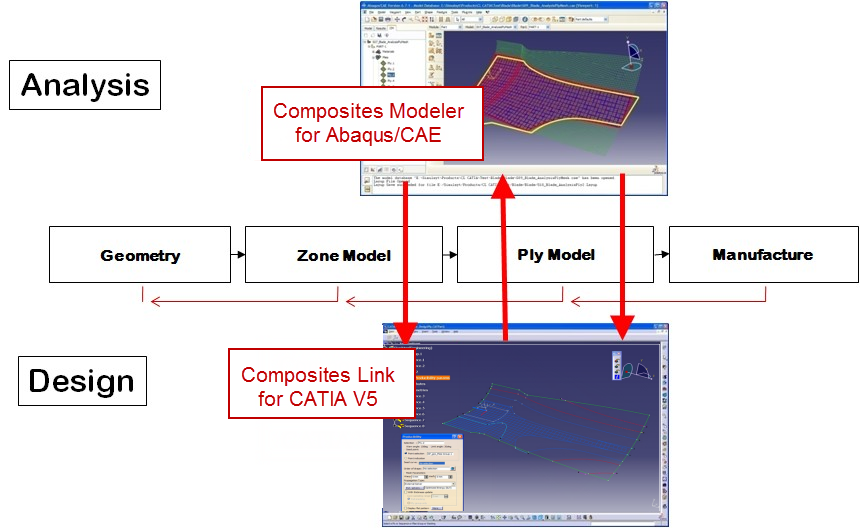
- The initial zone model is imported into CATIA to create zone descriptions of the model.
- The designer transforms these zones into a detailed ply model.
The ply model incorporates manufacturing requirements and detailed features like ply drop-offs. - As the designer has effectively changed the initial model, it
is essential to re-analyze the detailed model.
Therefore, plies are exported to the analysis environments via a Layup (or Nastran, Ansys CDB or XML) file, and the analyses re-run using the updated ply model. - If the detailed ply model no longer meets analysis requirements, the analyst can add plies in the analysis environment as required.
- Finally, any update is imported back into CATIA so the designers can update the reference model.
![]()