Read About Forming Simulations and About the Forming Process for more information.
-
Click Producibility for Forming
 .
.
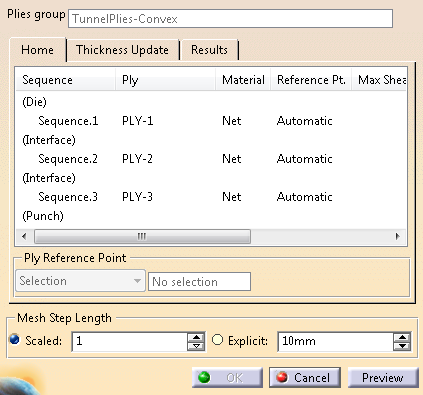
Select TunnelPlies-Convex under TunnelForming as the Plies group.
The plies are listed in the same order as in the plies group.
Rows named Die, Interface and Punch are added to visualize results such as sliding
(Sliding is a property of interfaces between plies).
-
Select PLY-1.
In the list under Ply Reference Point, select Selection.
Select Selection Point (Producibility) under Forming-Simulation > FLATTEN PLANE.
Repeat for each ply.
Other options are:- Indication: Pick a location in the graphic area.
- Automatic: The reference point is the geometric center of the ply.
-
A mesh will be created.
Under Mesh Step Length, select Explicit and enter 8mm.
Mesh Step Length is used to compute the simulation mesh.
It can be:- Scaled: The step length is a ratio computed from the size of each ply.
- Explicit: You enter a value.
-
Click Preview.
- The simulation is run separately on each ply.
- The maximum shear and maximum deviation for each ply are listed in the table
-
Go to Results.
Select a ply under Selection to start its post-processing. -
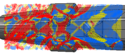
To analyze the amount of shear resulting from the forming simulation:
- Under Display Result, select Shearing angle from the list.
- Under Display Geometry, select Producibility Mesh.
-
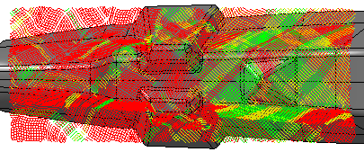
Select Deviation from the list to analyze the amount of deviation between the actual and theoretical fiber directions.
-
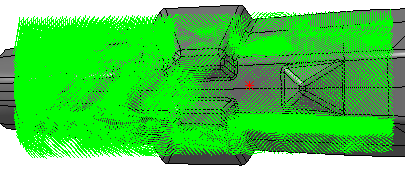
To analyze the amount of sliding that occurs during the forming process:
- Select an interface between two plies.
- Select Sliding from the list.
- Select Vectors under Display Geometry.
-
Validate to store the quick forming simulation, as Forming under the plies group.
-
After a modification of the model shape:
- Double-click Forming.
- Click Preview to update the simulation.
- Review the model as explained above.
![]()