Quick Forming Simulation
Producibility for Forming proposes a quick simulation, sufficient at the early stage of design.
Using kinematics and inverse solvers, Quick simulation for Hand Layup (or Draping)
is
very effective at modeling deformation of biaxial/uniaxial and
isotropic/orthotropic materials respectively. However, for Hand Layup, the material
effectively sticks to the surface at the Seed Point, with shear
building up progressively from this point. The result is strongly dependent on the location of the Seed
Point, and impacts the manufacturing experience.
Hand Lay-up: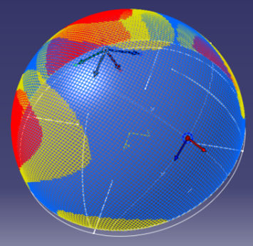
In contrast, during the forming process, the blanks slide relative to each other and to the mold, each in a very complex way. A detailed calculation of this takes hours and requires accurate material and friction data, whereas it not required nor appropriate during the initial design. A quick but representative simulation is necessary and sufficient at this stage.
In the absence of external constraints apart
from a 3D shape, sheet materials tend to distort to minimize the global elastic energy in the sheet.
Therefore, Composites Forming provides a quick solution that minimizes the shear strain
energy in the sheet for a given material direction at the
Reference Point. This quick solution reflects the
effect of blank size and surface geometry. The material is allowed to shear at the Reference Point:
Its location is not critical but is conveniently located near the
middle of the ply. For the case of a symmetrical geometry like a hemisphere, the
result is always symmetrical whatever the Reference Point, as expected to
minimize global shear strain energy.
Forming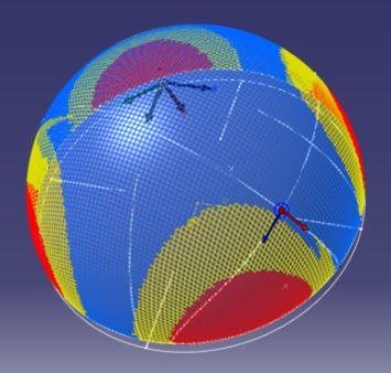
Detailed Forming Simulation
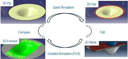
Composites Forming provides an easy detailed forming simulation.
The detailed simulation model is generated automatically from the quick simulation results with
- Seamless remeshing to access more detailed simulations needed as the design matures.
- A direct link between the simulation results and the design model to allow optimization.
- Access within the design context to allow use by composites engineers without specialist training and experience.
Supported Materials
Composites materials used for forming can be characterised as
- Directional, where the deformation of the fabric is strongly influenced by reinforcing fibres that lie in one or two principal directions, typical examples being woven fabrics and most uniaxial and biaxial Non-crimp fabrics (NCFs). In these materials, the reinforcing fibres can be considered inextensible and deformation during forming results mainly from shearing between the fibres. These materials drape easily and in-plane deformation can be modelled using the Pin-jointed Net (PJN) model.
- General, where there are no obvious preferential modes of deformation and the material deforms as a function of load state and history. Typical general materials include foam, rubber, leather, random mats and triaxial or quadraxial NCFs. These materials are much less drapable than directional materials and require complex, custom material models although isotropic or orthotropic models may be acceptable for initial studies.
Material model supported by the quick simulation include:
- Pin-Jointed Net (PJN) with a kinematic solver for biaxial and uniaxial directional materials..
- Isotropic/orthotropic, with an inverse solver for general materials.
Detailed simulation supports a wide variety of material models.
Following material models are compatible with the quick simulation for the preliminary calculation:
- PJN using VFABRIC for in-plane deformation and a separate element allowing the addition of bending stiffness.
- Isotropic/orthotropic materials.
A simple indentation test can be used to check the validity of the PJN model for directional materials.
- Example of valid PJN - Biaxial NCF (good forming)
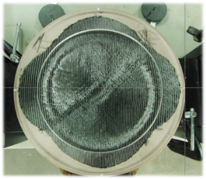
- Example of invalid PJN - Quadraxial NCF (bad forming, wrinkling)
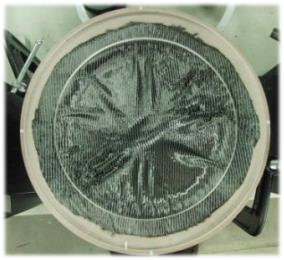
Easily drapable fabrics such as biaxial and uniaxial NCFs tend to follow PJN models closely, leading to their widespread use.
For complex materials, detailed simulations using Abaqus Explicit supports material models (using VUMATs) that do not follow the standard models. These models are typically developed by universities, research institutes and materials experts with the capability to characterize material behavior, develop a matching material model and determine the material parameters for the models.
Material Characterization
Detailed simulations require a correct characterization of materials, even with relatively simple material models.
This involves testing the material and calculating the material properties.
For a PJN material, following measurements are necessary:
- In-plane stiffness, measured using a bias-extension test or a picture frame test.
- Bending stiffness, typically measured according to ASTM D1388 and reduced to useful bending stiffness using a nonlinear bending calculation.
- Friction between mold and material, and between two materials. The closer the test approaches the real world contact situation, the better the result is. For more general materials, especially those requiring custom materials models, very complex material characterization is necessary depending on the form of the material model.
![]()