Constraints
Constraints are defined on the analysis degrees of freedom between regions of a model. The following sections discuss the constraints available in Nonlinear Structural Analysis:
 Creating
Rigid Body Constraints: Constrains the motion of
regions of a part so that the relative positions of points in
the region remain constant throughout the analysis, prohibiting
deformation.
Creating
Rigid Body Constraints: Constrains the motion of
regions of a part so that the relative positions of points in
the region remain constant throughout the analysis, prohibiting
deformation.
 Creating Rigid
Couplings: Constrains selected degrees of freedom
of a region of a part by coupling the motion of the region to
the rigid body motion of a handler point.
Creating Rigid
Couplings: Constrains selected degrees of freedom
of a region of a part by coupling the motion of the region to
the rigid body motion of a handler point.
 Creating Smooth
Couplings: Constrains selected degrees of freedom
of a region of a part by coupling the motion of the region to
the translation and rotation of a handler point.
Creating Smooth
Couplings: Constrains selected degrees of freedom
of a region of a part by coupling the motion of the region to
the translation and rotation of a handler point.
 Creating Rigid Body
Constraints
Creating Rigid Body
Constraints
A rigid body constraint allows you to constrain the motion of selected parts and points so that the relative positions of points in the body remain constant throughout the analysis, prohibiting deformation. A rigid body will, therefore, have three free translational and three free rotational motions; these motions can be prescribed by applying boundary conditions to the rigid body. If no boundary conditions are applied, the body will behave as a free rigid body.
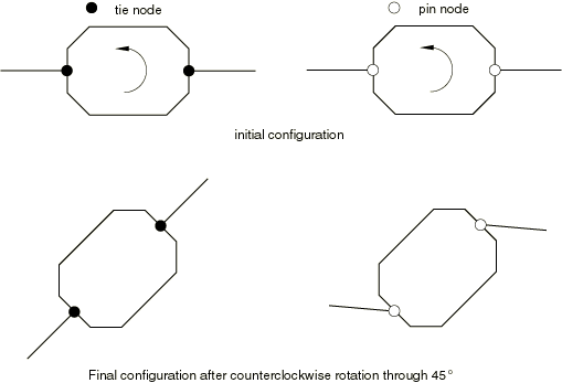
Rigid bodies can consist of three-dimensional bodies, groups of points, or a combination of bodies and points. The points can be connected to other, deformable bodies. Points that are part of a rigid body can be defined as either tie nodes or pin nodes. A tie node transmits both translational and rotational degrees of freedom to any body to which it is attached. A pin node transmits only translational degrees of freedom to any body to which it is attached. Figure 7–1 illustrates the difference between the two node types. Points on either end of the octagonal rigid body are connected to deformable bodies. When the rigid body is rotated, the deformable bodies attached to tie nodes rotate as well, while the deformable bodies attached to pin nodes displace while retaining their rotational orientation.
You can specify the handler, or reference point, for the rigid body constraint by selecting a vertex or by selecting a point group (containing a single point). You can instruct Nonlinear Structural Analysis to redefine the handler point at a point corresponding to the calculated center of mass of the rigid body during the analysis; any boundary conditions applied to the handler point will then act on the rigid body's center of mass. If you do not specify a handler point, Nonlinear Structural Analysis creates it at the approximate centroid of the selected parts;the solver moves the handler from the approximate centroid to the calculated center of mass during the analysis.
Rigid body constraints are available only in the Nonlinear Structural Analysis workbench.
![]() This task shows you how to create a rigid body
constraint.
This task shows you how to create a rigid body
constraint.
-
Click the Rigid Body Constraint icon
.The Rigid Body Constraint dialog box appears. A Rigid Body Constraint object appears in the specification tree under the Connections objects set for the Initialization step, and a Rigid Body Constraint Connection Mesh appears under the Nodes and Elements objects set.
-
You can change the identifier of the constraint by editing the Name field.
-
If desired, select the part or parts to constrain in the window or in the specification tree.
The Support field is updated to reflect your selection.
-
If desired, select vertices or points to act as pin nodes in the rigid body.
The Pin points support field is updated to reflect your selection.
-
If desired, select vertices or points to act as tie nodes in the rigid body.
The Tie points support field is updated to reflect your selection.
-
If desired, select a vertex or point group to represent the handler point.
The Handler field is updated to reflect your selection.
-
To move a selected handler point to the center of mass of the rigid body during the analysis, toggle on Move to center of mass.
-
Click OK in the Rigid Body Constraint dialog box.
Symbols representing the rigid body constraint appear on the corresponding parts.
Creating Rigid
Couplings
A rigid coupling allows you to eliminate selected degrees of freedom from a part or from regions of a part by coupling the motion of a region to the motion of a handler, or reference point. You can use a rigid coupling to model end conditions; for example, modeling a rigid end plate or modeling plane sections of a solid to remain planar. If you eliminate all three translational degrees of freedom, the part or region behaves as a rigid body.
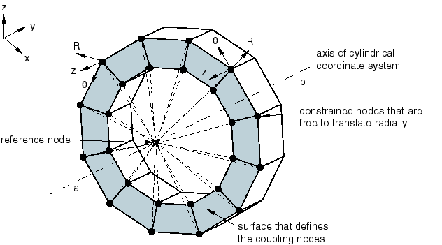
Figure 7–2 shows a part that was twisted by creating a rigid coupling between a handler point and a surface at one end of the part and then rotating the handler point about the axis of a local cylindrical coordinate system. The rigid coupling was defined using the same coordinate system, and the nodes on the surface at the end of the part are free to move in the radial direction.
You can specify the handler for a rigid coupling by selecting a vertex, a point, or a point group (containing a single point). If you do not specify the handler point, Nonlinear Structural Analysis selects one of the vertices from the part or region.
After you have selected the support regions for the rigid coupling, you can exclude subregions from your selection. For example, you can select a face as the support region and then exclude one or more edges of the face from the rigid coupling. You can exclude an edge by selecting it directly or by excluding a second face that shares the same edge. If necessary, you can exclude a region to avoid overconstraining your model. For example, you may need to exclude regions that you defined as rigid bodies and regions to which you have applied boundary conditions.
Rigid couplings are available only in the Nonlinear Structural Analysis workbench.
By default, the constrained degrees of freedom are associated with the global, rectangular Cartesian axis system. You can specify a local coordinate system for the degrees of freedom, and you can define the local system as a Cartesian, cylindrical, or spherical axis system. Local coordinate systems are defined in the CATIA Part Design workbench.
![]() This task shows you how to create a rigid coupling.
This task shows you how to create a rigid coupling.
-
Click the Rigid Coupling icon
.The Rigid Coupling dialog box appears. A Rigid Coupling object appears in the specification tree under the Connections objects set for the Initialization step, and a Rigid Body Coupling Connection Mesh appears under the Nodes and Elements objects set.
-
You can change the identifier of the constraint by editing the Name field.
-
In the window or in the specification tree, select the geometry support. Any selectable geometry is highlighted when you pass the cursor over it. You can select several supports to apply the rigid coupling to all supports simultaneously.
The Supports field is updated to reflect your selection.
-
Select regions from which the rigid coupling will be excluded.
The Exclusion Regions field is updated to reflect your selection.
-
Select a vertex, point, or point group to represent the handler point.
The Handler field is updated to reflect your selection.
-
Toggle on a degree of freedom to constrain it. Toggle off a degree of freedom to leave it unconstrained.
-
If desired, toggle on Selected local system, and select a coordinate system to define local directions.
You can also select the orientation of the local system. Choose from Cartesian, Cylindrical, or Spherical. See Using Local Coordinate Systems for more information.
-
Click OK in the Rigid Coupling dialog box.
Creating Smooth
Couplings
A smooth coupling is similar to a rigid coupling in that it couples the motion of a region to the motion of a handler, or reference point. A rigid coupling allows you to eliminate both rotational and translational degrees of freedom. In contrast, a smooth coupling allows you to eliminate only rotational degrees of freedom—it always constrains the translational degrees of freedom. In addition, a smooth coupling constraint distributes loads such that the resultants of the forces (and moments) in the selected region are equivalent to the forces and moments at the handler point. A smooth coupling is enforced in an average sense in a way that enables control of the transmission of loads through weight factors at the selected region. Nonlinear Structural Analysis applies a uniform weight factor (1.0) to the region.
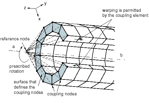
Figure 7–3 shows a part that was twisted by creating a smooth coupling between a handler point and a surface at one end of the part and then rotating the handler point about the Z-axis. The surface at the end of the part warps and deforms along the Z-axis, although the resultant of all the forces on the surface is zero. If you applied a rigid coupling in a similar manner, the surface at the end of the part would remain planar, and it would simply rotate about the Z-axis.
You can specify the handler for a smooth coupling by selecting a vertex, point, or point group (containing a single point). If you do not specify the handler point, Nonlinear Structural Analysis selects one of the vertices from the part or region.
After you have selected the support regions for the smooth coupling, you can exclude subregions from your selection. For example, you can select some faces as the support regions and then exclude the edges of those faces from the smooth coupling. If necessary, you can exclude a region to avoid overconstraining your model. For example, you may need to exclude regions that you defined as rigid bodies and regions to which you have applied boundary conditions. You can select an exclusion region that touches the support region but does not intersect it. For example, if two faces touch along a common edge and you selected one face as the support region and the second face as the exclusion region, the effect is to exclude the common edge.
Smooth couplings are available only in the Nonlinear Structural Analysis workbench.
By default, the constrained degrees of freedom are associated with the global, rectangular Cartesian axis system. You can specify a local coordinate system for the degrees of freedom, and you can define the local system as a Cartesian, cylindrical, or spherical axis system. Local coordinate systems are defined in the CATIA Part Design workbench.
![]() This task shows you how to create a smooth coupling.
This task shows you how to create a smooth coupling.
-
Click the Smooth Coupling icon
.The Smooth Coupling dialog box appears. A Smooth Coupling object appears in the specification tree under the Connections objects set for the Initialization step, and a Smooth Coupling Connection Mesh appears under the Nodes and Elements objects set.
-
You can change the identifier of the constraint by editing the Name field.
-
In the window or in the specification tree, select the geometry support. Any selectable geometry is highlighted when you pass the cursor over it. You can select several supports to apply the smooth coupling to all supports simultaneously.
The Supports field is updated to reflect your selection.
-
Select regions from which the smooth coupling will be excluded.
The Exclusion Regions field is updated to reflect your selection.
-
Select a vertex, point, or point group to represent the handler point.
The Handler field is updated to reflect your selection.
-
Toggle on a rotational degree of freedom to constrain it. Toggle off a rotational degree of freedom to leave it unconstrained. All translational degrees of freedom are constrained.
-
If desired, toggle on Selected local system, and select a coordinate system to define local directions.
You can also select the orientation of the local system. Choose from Cartesian, Cylindrical, or Spherical. See Using Local Coordinate Systems for more information.
-
Click OK in the Smooth Coupling dialog box.