Creating Smooth Couplings
A smooth coupling is similar to a rigid coupling in that it couples the motion of a region to the motion of a handler, or reference point. A rigid coupling allows you to eliminate both rotational and translational degrees of freedom. In contrast, a smooth coupling allows you to eliminate only rotational degrees of freedom—it always constrains the translational degrees of freedom. In addition, a smooth coupling constraint distributes loads such that the resultants of the forces (and moments) in the selected region are equivalent to the forces and moments at the handler point. A smooth coupling is enforced in an average sense in a way that enables control of the transmission of loads through weight factors at the selected region. Abaqus for CATIA V5 applies a uniform weight factor (1.0) to the region.
Figure 7–3 shows a part that was twisted by creating a smooth coupling between a handler point and a surface at one end of the part and then rotating the handler point about the Z-axis. The surface at the end of the part warps and deforms along the Z-axis, although the resultant of all the forces on the surface is zero. If you applied a rigid coupling in a similar manner, the surface at the end of the part would remain planar, and it would simply rotate about the Z-axis.
See Coupling constraints in the Abaqus Constraints Guide for a detailed description of smooth (or distributing) couplings.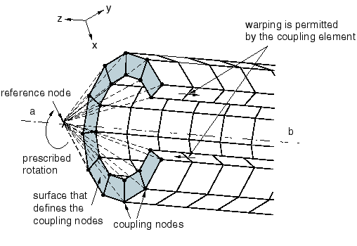
You can specify the handler for a smooth coupling by selecting a vertex, point, or point group (containing a single point). If you do not specify the handler point, Abaqus for CATIA V5 selects one of the vertices from the part or region.
After you have selected the support regions for the smooth coupling, you can exclude subregions from your selection. For example, you can select some faces as the support regions and then exclude the edges of those faces from the smooth coupling. If necessary, you can exclude a region to avoid overconstraining your model. For example, you may need to exclude regions that you defined as rigid bodies and regions to which you have applied boundary conditions. You can select an exclusion region that touches the support region but does not intersect it. For example, if two faces touch along a common edge and you selected one face as the support region and the second face as the exclusion region, the effect is to exclude the common edge.
Smooth couplings are available only in the Nonlinear Structural Analysis workbench.
By default, the constrained degrees of freedom are associated with the global, rectangular Cartesian axis system. You can specify a local coordinate system for the degrees of freedom, and you can define the local system as a Cartesian, cylindrical, or spherical axis system. Local coordinate systems are defined in the CATIA Part Design workbench.
This task shows you how to create a smooth coupling.
Click the Smooth Coupling icon
 .
.The Smooth Coupling dialog box appears. A Smooth Coupling object appears in the specification tree under the Connections objects set for the Initialization step, and a Smooth Coupling Connection Mesh appears under the Nodes and Elements objects set.
You can change the identifier of the constraint by editing the Name field.
In the window or in the specification tree, select the geometry support. Any selectable geometry is highlighted when you pass the cursor over it. You can select several supports to apply the smooth coupling to all supports simultaneously.
The Supports field is updated to reflect your selection.
Select regions from which the smooth coupling will be excluded.
The Exclusion Regions field is updated to reflect your selection.
Select a vertex, point, or point group to represent the handler point.
The Handler field is updated to reflect your selection.
Toggle on a rotational degree of freedom to constrain it. Toggle off a rotational degree of freedom to leave it unconstrained. All translational degrees of freedom are constrained.
If desired, toggle on Selected local system, and select a coordinate system to define local directions.
You can also select the orientation of the local system. Choose from Cartesian, Cylindrical, or Spherical. See Using Local Coordinate Systems for more information.
Click OK in the Smooth Coupling dialog box.