Creating Rigid Couplings
A rigid coupling allows you to eliminate selected degrees of freedom from a part or from regions of a part by coupling the motion of a region to the motion of a handler, or reference point. You can use a rigid coupling to model end conditions, for example, modeling a rigid end plate or modeling plane sections of a solid to remain planar. If you eliminate all three translational degrees of freedom, the part or region behaves as a rigid body.
Figure 7–2 shows a part that was twisted by creating a rigid coupling between a handler point and a surface at one end of the part and then rotating the handler point about the axis of a local cylindrical coordinate system. The rigid coupling was defined using the same coordinate system, and the nodes on the surface at the end of the part are free to move in the radial direction.
See Coupling constraints in the Abaqus Constraints Guide for a detailed description of rigid (or kinematic) couplings.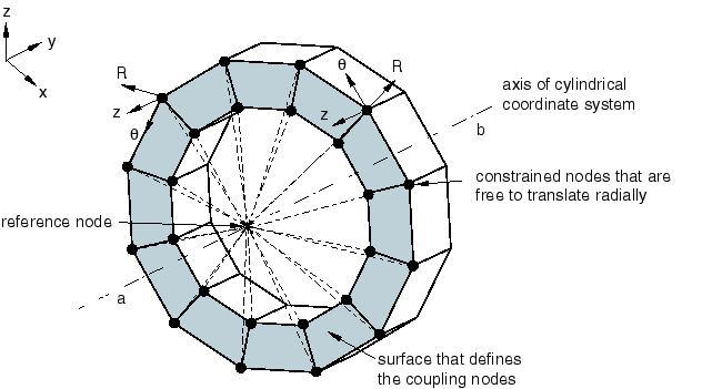
You can specify the handler for a rigid coupling by selecting a vertex, a point, or a point group (containing a single point). If you do not specify the handler point, Abaqus for CATIA V5 selects one of the vertices from the part or region.
After you have selected the support regions for the rigid coupling, you can exclude subregions from your selection. For example, you can select a face as the support region and then exclude one or more edges of the face from the rigid coupling. You can exclude an edge by selecting it directly or by excluding a second face that shares the same edge. If necessary, you can exclude a region to avoid overconstraining your model. For example, you may need to exclude regions that you defined as rigid bodies and regions to which you have applied boundary conditions.
Rigid couplings are available only in the Nonlinear Structural Analysis workbench.
By default, the constrained degrees of freedom are associated with the global, rectangular Cartesian axis system. You can specify a local coordinate system for the degrees of freedom, and you can define the local system as a Cartesian, cylindrical, or spherical axis system. Local coordinate systems are defined in the CATIA Part Design workbench.
This task shows you how to create a rigid coupling.
Click the Rigid Coupling icon
 .
.The Rigid Coupling dialog box appears. A Rigid Coupling object appears in the specification tree under the Connections objects set for the Initialization step, and a Rigid Body Coupling Connection Mesh appears under the Nodes and Elements objects set.
You can change the identifier of the constraint by editing the Name field.
In the window or in the specification tree, select the geometry support. Any selectable geometry is highlighted when you pass the cursor over it. You can select several supports to apply the rigid coupling to all supports simultaneously.
The Supports field is updated to reflect your selection.
Select regions from which the rigid coupling will be excluded.
The Exclusion Regions field is updated to reflect your selection.
Select a vertex, point, or point group to represent the handler point.
The Handler field is updated to reflect your selection.
Toggle on a degree of freedom to constrain it. Toggle off a degree of freedom to leave it unconstrained.
If desired, toggle on Selected local system, and select a coordinate system to define local directions.
You can also select the orientation of the local system. Choose from Cartesian, Cylindrical, or Spherical. See Using Local Coordinate Systems for more information.
Click OK in the Rigid Coupling dialog box.