Defining Film Conditions and Initial Conditions in a Heat Transfer Step
This task shows you how to enter the Thermal Analysis workbench, edit a heat transfer step, define film conditions, and define an initial temperature field. You will define film conditions for the inner and outer surfaces of a pipe intersection model, and you will apply an initial temperature to the entire pipe.
Select Start>Analysis & Simulation> Thermal Analysis from the main menu bar.
The New Analysis Case dialog box appears with the default Thermal Analysis type selected.
Click OK in the New Analysis Case dialog box to enter the Thermal Analysis workbench.
Warning: Do not select Keep as default starting analysis case in the New Analysis Case dialog box.
A .CATAnalysis document named Analysis1 opens. A link exists between the .CATPart and the .CATAnalysis document. In addition, the standard structure of the Analysis Manager specification tree is displayed.
The Thermal Case objects set contains a Simulation History objects set with an Initialization step and a Heat Transfer Step objects set, a Jobs objects set containing a default job, and empty Display Groups and Analysis Case Solution objects sets. The Simulation History will contain a description of the environmental influences on the model, which generally vary as a function of time over a period defined by the user. (See Specification Tree for more details on the specification tree.)
To edit the heat transfer step created with the analysis case, double-click on the Heat Transfer Step–1 objects set in the specification tree under the Simulation History objects set for the current analysis case. (The current analysis case is the one most recently created or edited; it is underlined in the specification tree.)
Abaqus for CATIA V5 opens the Heat Transfer Step dialog box.
Note: To create a new heat transfer step, you can click the Heat Transfer Step icon
 .
.You can change the step identifier by editing the Step name field. This name will be used in the specification tree.
Enter Computation of temperature distribution as the Step description. This description will appear in the input file that is written for this analysis.
Modify the Basic Step Data:
Enter a value of 200 seconds for the Step time.
Enter a value of 1 second for the Initial increment size.
Enter a value of 10 seconds for the Maximum increment size.
Modify the Heat Transfer Data:
Toggle on Transient as the Thermal response.
Toggle on End step when temperature change rate is less than, and enter a value of 0.5 Kdeg for this option.
Enter a value of 10 Kdeg for the Maximum temperature change allowed per increment.
Click OK when you have finished editing the step.
The Heat Transfer Step objects set contains a default Field Output Request object in a Field Output Request objects set and empty History Output Requests, Loads, and Boundary Conditions objects sets.
When defining a film condition, you must select all of the faces on the model to which the film condition applies. Defining surface groups simplifies the process of defining a film condition. A group is a preselected set of geometric entities that can be used as a support for model property definitions. Groups are saved in the specification tree and can be reused in multiple property definitions.
Click the Surface Group icon
 .
.The Surface Group dialog box appears, and a Surface Group object appears in the specification tree under the Groups objects set.
Enter OuterSurface in the Name field. This name appears in the specification tree as the identifier for the group.
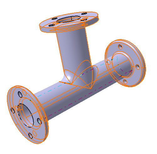
Select the 25 faces constituting the outer surface of the pipe, as shown in Figure 3–7.
Tip: It is easier to manipulate the model if the render style is set to Shading with Edges. From the main menu bar, select View>Render Style>Shading with Edges. Reselect a face to deselect it if necessary. There should be 7 faces on each of the left and right flanges, 5 faces on the top flange, and 6 faces on the main T-shaped cylinder.
Click OK when you have finished selecting the faces.
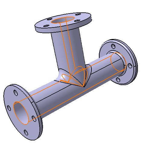
Repeat the above steps to create another group called InnerSurface that consists of the inner faces of the pipe. The inner surface is shown in Figure 3–8; it is composed of 6 faces.
Define the film conditions.
Click the Film Condition icon
 .
.The Film Condition dialog box appears.
You can change the identifier of the load by editing the Name field.
Select the OuterSurface group in the specification tree as the support for the load.
1 Face appears in the Support field to reflect your selection; however, the load will be applied to all 25 faces that are part of the OuterSurface group definition.
By default, the film coefficient is assumed to be a function of surface temperature. In this example the film coefficient is constant; therefore, toggle off Use temperature-dependent data, and enter a value of 50 W/m2K for the film coefficient.
Enter a value of 293 Kdeg for the Reference sink temperature.
Click OK in the Film Condition dialog box.
A Film Condition object appears in the specification tree under the Loads objects set for the current step, and symbols indicating the applied film condition are displayed on the selected faces.
Repeat the above steps to define the film condition for the inner surface of the pipe, using the InnerSurface group as the support, a film coefficient of 1200 W/m2K, and a reference sink temperature of 673 Kdeg.
Define the initial conditions.
Click the Initial Temperature icon
 .
.The Initial Temperature dialog box appears.
You can change the identifier of the field by editing the Name field.
Select the PartBody feature in the specification tree to apply the initial temperature to the entire model.
The entire part is highlighted, and the Supports field is updated to reflect your selection.
Use the default Uniform distribution type, and enter a value of 293 Kdeg for the Magnitude of the initial temperature.
Click OK in the Initial Temperature dialog box.
An Initial Temperature object appears in the specification tree under the Fields objects set in the Initialization step, and symbols indicating the applied temperature are displayed on the entire model.