Postprocessing and Cut Plane Analysis
In this task you will postprocess the results of the structural analysis.
For each step:
Right-click on the Static Step object under the Analysis Case Solution objects set in the specification tree, and select Generate Results Image from the menu that appears.
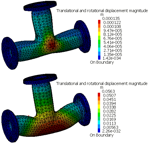
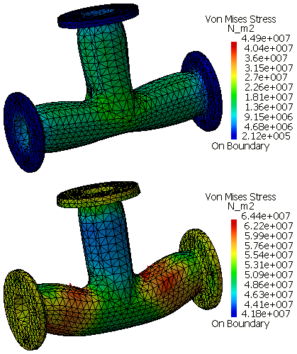
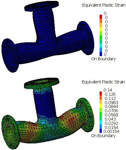
Successively select Translational and rotational displacement magnitude, Von Mises Stress, and Equivalent Plastic Strain from the list of Available Images and click OK to create the contour plots shown in Figure 3–12, Figure 3–13, and Figure 3–14.
Tip: By default, the previous image is deactivated from the display when you create a new contour plot image. To view a previously created image, right-click on the image name in the specification tree, and select Activate/Deactivate from the menu that appears. Use the same procedure to deactivate the current image if necessary.
Perform a cut plane analysis.
Click the Cut Plane Analysis icon
 .
.The cutting plane appears in the main window; in addition, the Cut Plane Analysis dialog box appears. The compass is positioned automatically on the model, and the cutting plane is positioned normal to the privileged direction of the compass.
Note: If the compass is already positioned in the view, the normal of the compass is considered to be the default normal of the cutting plane.
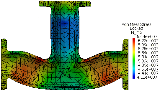
Rotate the cutting plane by clicking on the circular arcs of the compass and dragging the cursor; translate the cutting plane by clicking on the straight edges of the compass and dragging the cursor. Orient the cutting plane so that it cuts the pipe intersection in a plane parallel to the pipe axes, as shown in Figure 3–15.
As you modify the position of the plane, the results in the plane are updated automatically.