Defining Boundary Conditions
This task shows you to how to apply boundary conditions to constrain your part. You will fully constrain all degrees of freedom on two faces of the part and prescribe a vertical displacement for a third face.
Click the Clamp Boundary Condition icon
 .
.Tip: The Clamp Boundary Condition icon is hidden by default. The small black triangles at the base of some icons indicate the presence of hidden icons that can be revealed. Click the Displacement Boundary Condition icon
 , but do not release the mouse button. The Clamp Boundary Condition icon appears. Without releasing the mouse button, drag the cursor along the set of icons until you reach the Clamp Boundary Condition icon. Then release the mouse button to select that icon.
The Clamp BC dialog box appears, and a Clamp object appears in the specification tree under the Boundary Conditions objects set for the current step.
You can change the boundary condition identifier by editing the Name field.
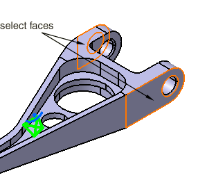
Select the two faces indicated in Figure 3–2 as supports for the boundary condition.
Tip: If necessary, reselect a face to remove it from the selection set.
The Supports field is updated to reflect your selection, and clamp symbols appear on the selected faces indicating the constrained degrees of freedom.
Click OK in the Clamp BC dialog box.
Click the Displacement Boundary Condition icon
.The Displacement BC dialog box appears, and a Displacement object appears in the specification tree under the Boundary Conditions objects set for the current step.
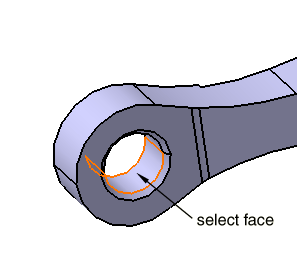
Select the face shown in Figure 3–3.
The Supports field is updated to reflect your selection, and arrows appear on the selected face indicating the constrained degrees of freedom (only the arrowheads appear for zero-valued constraints).
To prescribe a vertical displacement of 0.254 mm for the selected face, toggle off U1 and U2, enter a value of 0.254 mm for U3 in the Displacement BC dialog box, and click OK.