Assigning Continuum Shell Properties to Solids
Shell elements and membrane elements are used to model structures in which one dimension, the thickness, is significantly smaller than the other dimensions. Membrane elements are discussed in Assigning Membrane Properties to Surfaces. Two types of shell elements are available in Abaqus for CATIA V5: conventional shell elements and continuum shell elements. Conventional shell elements model a relatively thin surface by defining two-dimensional elements along with the shell normal direction. The nodes of a conventional shell element do not define the shell thickness; you specify the thickness of the shell when you assign a 2D Property to the shell. Continuum shell elements, on the other hand, resemble three-dimensional solid elements in that they model an entire three-dimensional body, and their thickness is determined from the element nodal geometry. However, continuum shell elements are formulated so that their kinematic and constitutive behavior is similar to conventional shell elements. Figure 8–8 illustrates the difference between conventional and continuum shell elements.
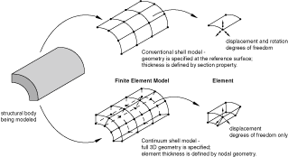
Conventional shell elements have displacement and rotational degrees of freedom; continuum shell elements have only displacement degrees of freedom. Continuum shell elements are more accurate in contact modeling than conventional shell elements, since they employ two-sided contact calculated at the surface of the element. Continuum shell elements also take into account changes in element thickness during contact. For thin-shell applications, conventional shell elements provide superior performance. See Shell elements: overview in the Abaqus Elements Guide, and Choosing a shell element in the Abaqus Elements Guide for more information.
Because continuum shell elements have a thickness direction associated with them, you must orient the elements correctly. You define the element stacking direction and thickness direction by assigning a material orientation to a 2D Property Enhancement and by specifying the approximate shell normal. The thickness direction strain is computed from the element nodal displacements, which in turn depend on the effective thickness modulus and the section Poisson's ratio. See Defining the thickness modulus in continuum shell elements in Using a general shell section to define the section behavior in the Abaqus Elements Guide for more information.
You assign continuum shell elements to a solid that has been meshed with either hexahedral or wedge elements. It is recommended that you create the continuum shell elements by meshing a face and by extruding the two-dimensional elements through the thickness of the solid. In effect, you are thickening a meshed shell. For example, you can use the Sweep 3D tool in the Advanced Meshing Tools workbench. Unlike conventional shells, continuum shell elements can be stacked through the thickness of the shell to provide more refined through-thickness response. A layer of a single element is adequate for capturing bending; however, stacking continuum shell elements allows for a richer transverse shear stress and force prediction.
Note: The results for Abaqus continuum shell elements are displayed as solid elements in Abaqus for CATIA V5. Therefore, you can display results for only the upper layer of continuum shells. For conventional shell elements, you can display results for the upper, mid, or lower layers.
Create a solid part in CATIA V5 along with an axis system that you will use to define the material orientation.
Apply a material to the part.
Use the Sweep 3D tool in the Advanced Meshing Tools workbench to mesh the solid by extruding a surface mesh of quadrilateral or triangular elements through the solid to a selected face.
Select Start>Analysis & Simulation>Nonlinear Structural Analysis from the menu bar to enter the Nonlinear Structural Analysis workbench. If necessary, set an empty analysis case or an analysis case that contains nonlinear structural analysis procedures to be the current case.
Create a 3D property, and select the solid part as the support for the 3D property.
Create a 2D property enhancement.
From the 2D Property Enhancement dialog box that appears, do the following:
Select the 3D Property that you created in the previous step as the support.
Click Edit to specify a material orientation. You must assign a material orientation; Abaqus for CATIA V5 does not assign a default orientation to continuum shells.
From the Assign Material Orientation dialog box that appears, do the following:
Choose a RECTANGULAR coordinate system type.
Select the axis system associated with the part.
Select the axis of the coordinate system that approximates the shell normal. This axis represents the shell thickness direction of a continuum shell.
If desired, specify a rotation of the projected coordinate system about the approximate shell normal.
Click OK to close the Assign Material Orientation dialog box.
Abaqus for CATIA V5 displays coordinate systems on the top and bottom faces of the extruded mesh. The n-axis indicates the shell normal (the stack direction); the 1- and 2-axes indicate the in-plane axes.
From the 2D Property Enhancement dialog box, click More and do the following:
Specify the Section Poisson's Ratio. In continuum shell elements specifying the section Poisson's ratio defines the thickness behavior for both small- and large-displacement analysis. Do either of the following:
Toggle on Use analysis default to indicate that the change in thickness is based on the element material definition.
Toggle on Specify value, and enter a value for the Poisson's ratio to cause the shell thickness to change as a function of membrane strains. This value must be between –1.0 and 0.5. A value of 0.0 will enforce constant shell thickness, and a negative value will result in an increase in the shell thickness in response to tensile membrane strains.
Specify the Thickness Modulus. Do either of the following:
Toggle on Use analysis default to allow Abaqus to compute the thickness modulus based on the initial elastic material properties. The default effective thickness modulus is twice the initial in-plane shear modulus based on the material definition.
Toggle on Specify value, and enter a value for the effective thickness modulus.
Click OK to close the 2D Property Enhancement dialog box.
Use the global or local element assignment tools to assign continuum shell elements to the extruded mesh. You can assign linear hexahedral elements (SC8R) or linear wedge elements (SC6R). See Modifying Global Element Assignments and Modifying Local Element Assignments for more information.
This task shows you how to use continuum shell elements.