Creating Bolt Tightening Connection Properties
A bolt tightening connection property takes into account pre-tension in bolt-tightened assemblies. The computation is carried out according to a two-step approach. In the first general static or explicit dynamics step of the analysis the model is submitted to tension forces due to bolt tightening by applying opposite forces on the bolt thread and on the support tapping, respectively. In general, the first step in your simulation history will not contain other loads, so the bolt tightening connection property can be evaluated and used as a precondition for the rest of the analysis. Then in the second step of the analysis the relative displacement of the two bolt surfaces (obtained in the first step) is fixed while further loading is applied to the model. If no general static or explicit dynamics steps are included in the analysis, the bolt is loaded in the first static linear perturbation step. Since bodies can be meshed independently, bolt tightening connection properties are designed to handle incompatible meshes.
Bolt tightening connection properties account for the elastic deformability of the interfaces.
A bolt tightening connection property is defined in terms of the two surfaces that may interact. These surfaces are indicated through the definition of an assembly constraint or an analysis connection. You can use an assembly constraint defined in the Assembly Design workbench to define the contact surface pairing between the bolt thread and the bolt support tapping. Alternatively, you can use a general analysis connection to define the contact surface pairing.For a description of the analysis connections that support bolt tightening connection properties, see the Generative Structural Analysis User's Guide. Table 6–3 summarizes the constraints that can be used to define a bolt tightening connection property.
Table 6–3 Bolt tightening connection properties.
| Assembly Design Workbench | Abaqus for CATIA V5 | |
|---|---|---|
| Coincidence Constraint | Contact Constraint | General Analysis Connection |
You can request history output of relative displacements and rotations and of total, elastic, viscous, and reaction forces and moments from a bolt tightening connection property. The support for the history output request is the connection mesh.
This task shows you how to create a bolt tightening connection property between two parts.
Click the Bolt Tightening Connection Property icon
 .
.The Bolt Tightening Connection Property dialog box appears. A symbol representing the bolt tightening connection property appears on the corresponding faces, and a Bolt Tightening Connection Property object appears in the specification tree under the Properties objects set.
You can change the identifier of the bolt tightening connection property by editing the Name field.
In the specification tree, select an assembly constraint created previously in the Assembly Design workbench or a general analysis connection created previously in Abaqus for CATIA V5.
The Supports field is updated to reflect your selection.
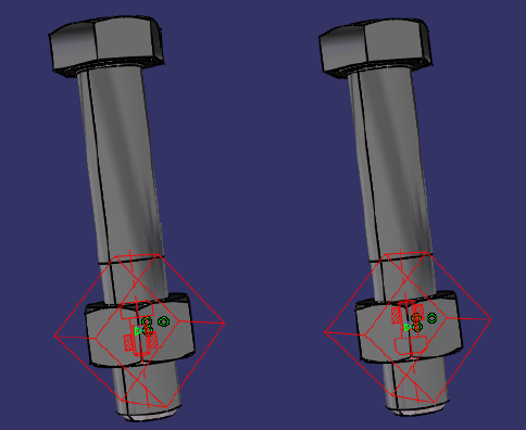
If necessary, modify the default values of the force and orientation parameters. Choose either the same or the opposite orientation so that the graphic representation of the bolt tightening connection property matches the bolt direction (see Figure 6–8). A positive force represents tightening.
Note: In some cases when the centers of the bolt and nut supports are aligned exactly, the graphic representation of the bolt may not be oriented properly. As a result, the bolt force may not be applied as intended. Abaqus for CATIA V5 will issue a warning message to inform you of these situations when you submit the simulation for analysis.
Click OK in the Bolt Tightening Connection Property dialog box.