")
|
This task describes
how to convert run into solid equivalent.
|
")
|
Raster views showing
the runs in each phase with the ISO standard color coding are used for
providing more readability and clarity for outfitters. However, the
section view generated from Drafting does not support the raster mode.
So, this causes some unwanted runs in the generated views. To avoid this
different sub-assemblies are created by breaking an existing run into
sub-assemblies. Each sub-assembly corresponds to a particular
drafting view. This leads to unnatural breaks in the runs. Also, doing
some modification on such runs is difficult. The Convert
RUN Into Solid command generates a solid representation
of selected runs under a given CATPart. These CATParts are
used to generate the required raster views. Here, the rib feature
generated is associated with the corresponding run. |
") |
1. |
Click Convert RUN Into Solid
") . .
The Convert RUN Into Solids dialog box appears.
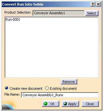
The current selected assembly is displayed in the Product Selection
box. |
| |
2. |
Click Select to choose another
assembly if required. All the runs under selected assembly are listed in the dialog box. |
|
3. |
Optional: Select the run and click Remove
to cancel the selected run. |
| |
4. |
Select Create new document. Note:
You can select the existing document to create the solid equivalent by
choosing the Existing document
option. |
|
5. |
In the File Name box, enter
the name of the new part. |
|
6. |
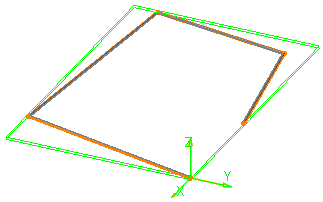
Click OK.
The solid equivalent is created for the selected RUN.
Since the Create new document
option is selected, a new CATPart sub-node appears in the specification tree under the system assembly node.
Note: If the Existing document
option is selected, then the solid equivalent is created in the existing
document. |
|
") |