You can check the result in WallSurfaceManager_EndP1.CATPart.
-
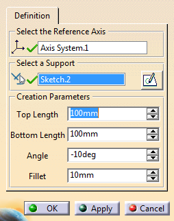
Select a support.
It can be
- A simple wireframe with one domain.
- A multi-domains wireframe, such as a sketch containing disconnected lines.
-
Alternatively, click Sketcher
 to create a multi-domains sketch.
 Under Creation Parameters, set required values.
- Top Length and Bottom Length manage the dimensions of the wall surface.
- Angle is the angle between the wall surface and the selected Z-axis.
- Fillet manages the fillet at the intersection of two wall surfaces.
Note: The parameters are used during creation, not to edit existing wall surfaces.
-
Click Apply.
- A wall surface is created on each domain of the selected support.
- If two domains intersect each other, a fillet is created at the intersection.
- By default, the longest fillet result is kept.
-
For individual edition, click a face of a fillet or of a wall surface and select Wall Surface Manager
 in the contextual toolbar.
 -
Click a face of a fillet and de-activate the fillet from the contextual toolbar.
The fillet is no longer taken into account.
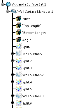
Under the Addenda Surface geometrical set, a Wall Surface Manager feature is created.
It contains Wall Surface features and Fillet
Surface features, with the related parameters.
They are automatically
generated when the Wall Surface Manager feature is updated.
![]()