Tips:
- When both G2/G1 are required, start with G2, check the result is correct, then continue with G1.
- Use Step back length to improve G2 quality.
You can check the result in SurfaceExtension_EndP1.CATPart.
-
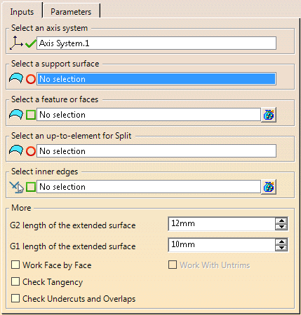
Click Surface Extention
 in the Part Extension toolbar.
-
On the selected surface, select:
- Either wires (Boundaries or stable split curves) to
extend on this surface.
Notes:- If you select a stable split curve, the support surface and the up-to-element (if any) are automatically detected.
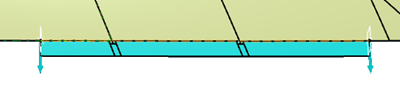
- You can orient or drag the planes delimiting the
work area to restrain it.
You can add a tangency constraint to the planes, with respect to an inside edge.
You can rotate the plane by editing the compass.
- Or faces to extend on this surface.
- Or nothing. In this case, all border faces are extended.
For best possible design change support, we recommend you select wires, especially stable split curves.
- Either wires (Boundaries or stable split curves) to
extend on this surface.
-
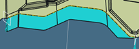
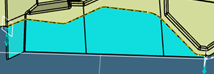
Optional: Select an up-to-element to trim the extended surface by this element (Enter G2 length of the extended surface and G1 length of the extended surface values).
- Without an up-to element
- With an up-to element
- Without an up-to element
-
Select inner edges to guide the G1 extrapolation.
If you are using a combination of G1 and G2 extrapolations, inner edges are retrieved on the G2 extrapolation.
Due to the instability of edges, design changes may lead to unexpected result. -
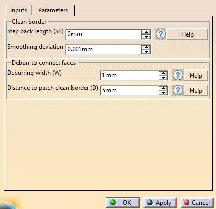
Go to the Parameters tab and set the values as required.
-
Back in the Inputs tab, under More, select further options as required.
Use Work Face by Face if the global method is not satisfactory.
-
Use Deburring width (W) and Distance to patch clean border (D) to clean the result.
Notes:
- If the result is not yet satisfactory, try working on a smaller or larger area.
- Trim back works better on flat faces.
-
As an alternative to extrapolating with a G2 length, select Work Face by Face and Work With Untrims.
The untrim is the support surface of the face.
In this mode, the untrim is trimmed by the boundaries of the input surface to compute a G2 extension.
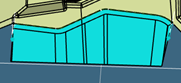
Below is an example of result combining Work With Untrims and Select Inner Edges.
-
If extension fails, errors are displayed, with a visualization of the problem to help you solve errors.
-
If required, check the tangency or the undercuts and overlaps.
A Surface extension feature (geometry) is created under the
Clean Contour node.
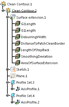
The
Surface extension feature contains the input parameters.
The
Clean Contour node contains the planes that limit the extension, if any.
AxisProfile corresponds to orientable planes delimiting the boundary.
It can be used to reduce or increase the area of the extension.
Note: Between several extended surfaces, G0, G1 nor G2 continuity cannot be guaranteed.
You may need to go to Generative Shape Design to connect several extended surfaces.
![]()