 |
-
Click
Create Press Direction
 in the Process Part Separtion
toolbar.
in the Process Part Separtion
toolbar.
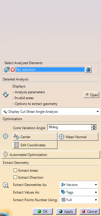
If the check box
Display detailed text in dialog in Tools/Options/Mechanical
Design/Die Face Design is cleared, the dialog box looks like this:
If the check box Display detailed text in dialog in
Tools/Options/Mechanical Design/Die Face Design is selected, the
dialog box looks like this:
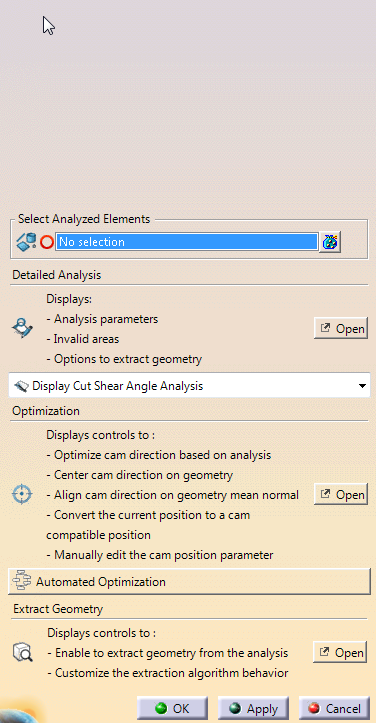
When required, click Open to access the
dialog boxes.
|
-
Select the elements to analyze.
The selection determines the proposed analyses:- Draft
and Depth analyses when only surfaces are selected.
- Shear angle analysis when only wires are selected.
- Draft, Depth, Shear angle, Normals, 2D/3D Cut when both
surfaces and wires are selected.
|
-
Manage the analyses:
- Select an analysis from the list.
If only wires
are selected, a support surface may be required to perform
some analyses.
Some surfaces are automatically retrieved.
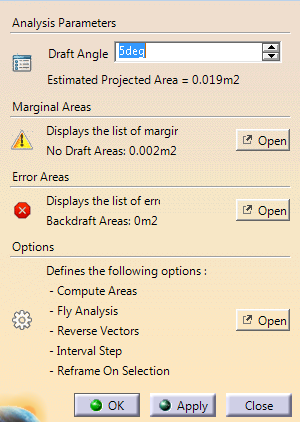
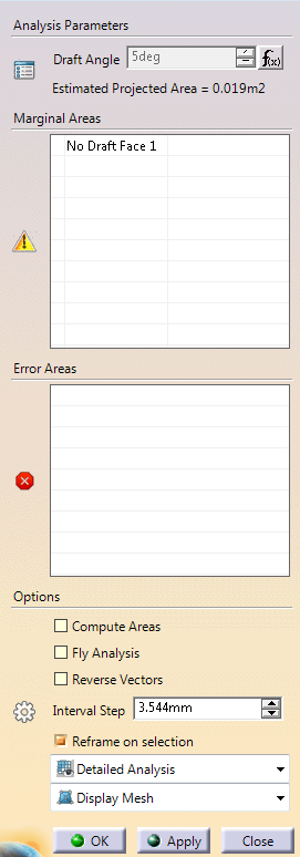
- Click Detailed Analysis.
or
- Follwo the messages or labels to check and correct
errors.
- When necessary, edit the Options to modify
the analysis behavior.
|
-
Go to the Optimization section to optimize the cam
direction with respect to the displayed analyses.
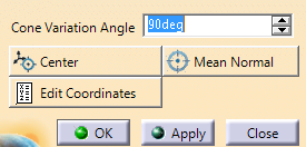
- Cone Variation Angle: Defines an angle
around the current position to compute the best position.
- Center: Centers the axis origin on the
analyzed elements. If surfaces and wires are selected, only
curves are taken into account.
- Mean Normal: Computes the mean normal of the
elements to align the Z-Axis on this normal.
- Edit Coordinates: Edits the coordinates of
the compass.
- Convert to Cam: Converts the current position
of the compass into a cam compatible solution.
|
-
Click Automated Optimization to center the
axis on the analyzed elements, find the best solution within a given
cone variation angle and convert the computed best solution to a cam
compatible solution.
-
Go to Extract Geometry to convert the results of the
displayed analysis to dead geometry.
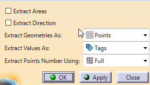
- Extract Areas: Results are stored as dead geometries
and 3D labels.
- Use Local Minima and Maxima for Extract Areas: The
number and locations of the 3D labels are optimized to match
the extremum analysis values.
- Extract Analyses as Points
- Extract Direction: Extracts the Z-Axis on each analyzed
point.
|
|