 |
-
Click
Process Export
 in the Process Definition toolbar.
-
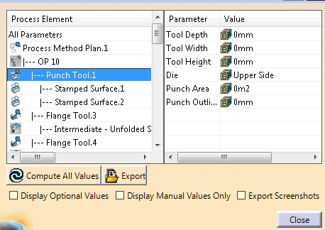
In the table only the not filled values are displayed by
default.
- Click All Parameters on the left to
display all parameters and their value on the right.
- Double-click an element to refram on it in the work area
and display its parameters and values.
- Select the required check boxes to manage the display of
parameters in the table.
By default, - Only the values
declared as mandatory in the configuration file are
displayed.
- All values (Computed by Die Face Design or entered by
you) are displayed.
|
-
Click Compute All Values to do so.
Parameters values are computed from their ID and previous definition.
-
Select Export Screenshots to export them as .png files.
|
You can customize the 3D scene before taking the screenshot.
After
the standard XML export is done, ou are asked to take screenshots - Of a global
process view of all method plans if several exist
- Then of each method plan process
- Then of each OP.
PNG files are created and
stored next to the xml file created by the export, under the
following paths: - Export_xml.xml: Reference XML file
created by the Export
- Export_xml.xml_screenshots: Main screenshot directory,
created next to the xml file.
- Process.png: Only if several method plans, combined
view of all method plans.
For example:
- Process Method Plan.1: Name depends on the feature
name in the specification tree.
- Process.png: Global view of this process method
plan.
- OP 10.png: View of OP10 of this method plan.
- OP 20.png
- OP 30.png
- ...
- Process Method Plan.2
- Process.png
- OP 10.png
- OP 20.png
- OP 30.png
- ...
|
-
Click Export and enter a path.
|
The data are saved in a XML file that contains
- The specified values.
- Position values for each operation step.
- The axis system coordinates.
|
|
|
|
About the Configuration File
The configuration file describes the attributes created on each feature
of the process and can be customized.
It contains one root node
<Attributes>. Under this node are listed all the attributes nodes to
be converted into knowledge parameters in Die Face Design data model. For
example:
<Attribute Target="MethodPlan" ID="MethodPlan_UserName"
DisplayName="Name, Departement" DefaultValue="" Level="1" Type="STRING"/>
The node name must be Attribute.
Attributes specify where
the knowledge parameter is created, as well as some other information.
- Target
- This is the parent of the parameter. It can be:
- MethodPlan (Process Method Plan Feature).
- Tool (Process Action/Tool).
- Operation (Process Step).
- AxisSystem (Axis System).
- SubTarget
- Used as type filter. It can be:
- Cam for AxisSystem
and Tool target, to specify that the parameters is only for cam axis
system/tools on cams.
- FoldType for Tool target and flanging tool.
- CutType for Tool target and cutting tool.
- Additional for Tool target and additional tool.
- Die for Tool target and die tool.
- DieInsert for Tool target and die insert tool.
- PunchInsert for Tool target and punch tool.
- BlankHolder for Tool target and blank holder tool.
- ID
- It is unique. Some IDs are automatically computed.
- MethodPlan_Material: Materials of
blank, separated by ; if several.
- MethodPlan_Thickness:
Thicknesses, separated by ; if several.
- MethodPlan_NbSteps: Nb of
process steps.
- MethodPlan_PartAreas: Areas of input parts.
- MethodPlan_Name: CATIA Part Name.
- Tool_Depth: Computed max depth
of the drawn area in the draw direction.
- Tool_Width: Dimension of
the drawn area along tool X direction.
- Tool_Height:
Dimension of the drawn area along tool Y direction.
- Tool_Punch_Area: Computed area of draw punch. If no detailed geometry,
uses the area of the drawn area.
- Tool_Punch_Outline: Dimension of
the boundary of the punch. If no detailed geometry, uses the length of
the drawn area boundary.
- Tool_Binder_Area: If a detailed geometry
is provided, uses the area of the specified geometry.
- Tool_Die_Area: Sum of all Tool_Binder_Area and Tool_Punch_Area of the same OP.
- Tool_Cut_Type: type of cut. Automatically set to outer or inner. Other
types are manual.
- Tool_Cut_Length: Length of the cut area,
including scrap area.
- Tool_Cut_NbRoundHoles: Nb of cut round holes.
- Tool_Cut_NbFormHoles: Nb of cut free form holes.
- Tool_Cam_Slope: Angle from the cam Z direction to the press table.
- Tool_Forming_Area: Area of the formed area.
- Tool_Forming_Edge_Length: Length of the folding line, intersection of
the formed area and the fixed area.
- DisplayName
-
Parameter
display name.
- DefaultValue
-
Parameter default value
- Level
-
If 1, value is needed for export. Otherwise it is not mandatory.
- Type
- Knowledge Type
- Values
- For type COMBO, list of
possible values.
Example of XML Export File
See CostExport.txt for an example of
content of the xml file.
|