-
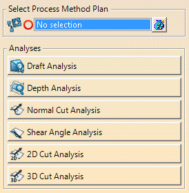
Press any analysis name, and enter the required values.
For Enter the value of Quick Draft Analysis Draft Angle Quick Depth Analysis Maximum depth Quick Cut Normals Analysis Normal angle Quick Cut Shear Analysis Shear angle Quick Cut 2D Analysis Value above, Value below, Value marginal 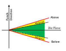
Quick Cut 3D Analysis Value above, Value below, Value marginal - The global parameters are directly created under the Process Method Plan, under the DFD Process Body.
- Relations are created between the global and local parameters of each analysis created in the process.
- The result of the cut analysis are available in Vectors and Acute/Obtuse modes outside the command.
-
Select the required analysis command from the Quick Analysis toolbar.
If a surface is required (Quick Cut Normals Analysis, Quick Cut 2D Analysis, Quick Cut 3D Analysis), the input surface of the trim partition is used for trim partition elements, the step geometry is used for process wireframes.
For Quick Display Press Table, Quick Display Stamp Partition, Quick Display Cut partition, Quick Display Process, the analyis direction is retrieved from the process definition. -
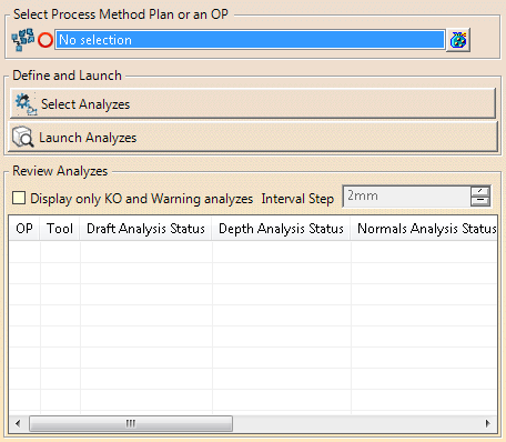
Select Review Quick Analysis
 .
.
-
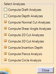
Press Select Analyses and the required check boxes.
-
Press Launch Analyses.
Created analyses are renamed according to input.
They are listed in the table, with their status. -
Edit the Interval Step used to tessellate the geometries to analyze, if required.
-
Select the Display only KO and Warning Analyses check box, if required.
![]()