-
Click Create OP Design Part
 in the Process Definition toolbar.
-
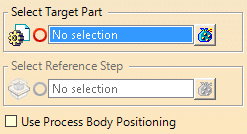
Select the part where you want to create the geometry.
-
Select the reference step.
-
If required, select the use Process Body Positioning check box.
When selected, the positions defined by the process body are used.
Otherwise, all the geometry is copied on the Method Plan position.
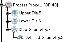
A Process Proxy geometrical set is created in the target part.
At synchronization, it generates three geometrical sets:
- One for the upper side of the die. It contains as many Tool proxies as they are tools in the process step, defined as being in the upper die in the concept process.Crea
- One for the lower side of the die. It contains as many Tool proxies as they are tools in the process step, defined as being in the lower die in the concept process.
- One for the step geometry. It contains the copy of the step geometry of the previous step.
The Tool Proxies are linked to the tools of the process step in the
concept part. At synchronization, they copy (Copy with Ref-Ref link) the
input geometry of the linked concept tool, the axis of the tool and the axis
of the press. They also generate a geometrical set named Detailed
Geometry to automatically retrieve the result detailed geometry of the
tool.
If a tool is removed from the concept, the corresponding Tool Proxy
is moved to a geometrical set named Unused Tool.
![]()