 |
-
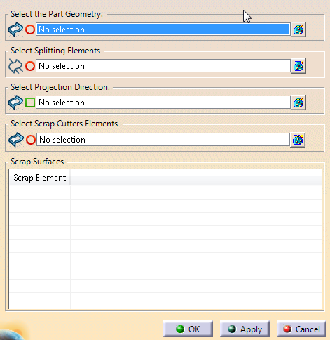
Click
Scrap Partition
 in the Process Part Separation toolbar.
-
Select
the Part Geometry (one or several surfaces to cut -Full Addendum in
our example).
-
Select
the Splitting Elements.
They can be:- A 3D curve projected on the surface to cut.
- A 2D Curve that defines a plane.
- 3D surfaces intersecting the surfaces to cut.
- Or a trim partition. Each element of the trim partition
is used as trim curve.
|
-
Select the Scrap Cutters elements
(wireframe).
Depending on the geometries inside the sketch that
defines the scrap cutters, geometries are extracted and computed with a
type (Scrap Hole or Scrap Line). This type can be changed from the
contextual menu.
-
Select the Projection Direction.
By default, the
projection is normal to the surface.
Results are listed under
Scrap Surfaces.
A Scrap Partition is created under
Partition Set in the specification tree
such as the red
surfaces below.
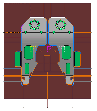
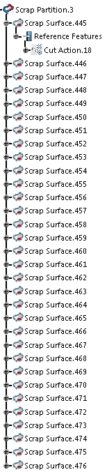
It
contains
Scrap Surface features, with reference features.
- A join is computed from the selected surfaces.
- A split of the join is computed for each trim curve.
- For each computed split, the smallest section is kept and added to
the results.
- The associated trim curve is displayed under Reference Features.
|