 |
-
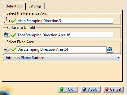
Click Unfold
 in the Process Part Separation toolbar.
-
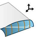
Select an axis system (stamping direction).
The
unfold orientation and angle are computed from the Z-Axis.
The mean
line or the folding line from axis is projected on its XY plane.
The
XY plane is used to compute a support surface, when none is selected.
-
Select the Surface to Unfold.
-
Select a
Fixed Area.
It is a surface or 3D curve that
intersects the surface to unfold.
The actual fixed area is specified
by all the edges of the surface
to unfold that lie entirely on the
fixed area.
These edges form the folding line.
-
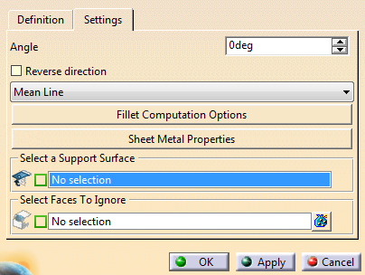
Optional: Go to the Settings tab and select a
Support Surface.
The unfold is projected - On the support surface, if
selected
- On an extrude of the folding line in the reference
XY plane otherwise.
|
-
Select the type of unfold to create:
- Unfold as Planar Surface: Unfolds the
selected surface as a planar surface, possiblbly on a
support.
- Unfold as Trim Line: Unfolds the selected
surface as a trim line, possibly on a support.
- Partial Unfold: Unfolds the selected surface
by keeping the inital geometry and recomputing a fillet.
|
-
Still in the Settings tab, set parameters as
necessary:
- Angle between the unfolded surface and the Z-Direction
of the selected axis system.
- Reverse direction
- Computation options for the folding line:
- Mean Line: The folding line is a line
computed between the first and the last points of the
folding line.
- Mean Line From Axis: The folding line is
the computed mean line projected on the reference XY
plane.
- Folding Line: The folding line is the
intersection between the fixed area and the surface to
unfold.

- Folding Line From Axis: The folding line
is the intersection between the fixed area and the
surface to unfold,
projected on the reference XY
plane.
-
Fillet Computation Options:
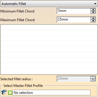
- No Fillet. This option is not available when
unfolding as spec.
- Automatic Fillet: Computes the fillet radius
automatically from the bend angle
- with the
specified maximum chord where the angle between the
tangent
of the surface to unfold and the Z-Direction
is minimum
- with the minimum chord where the angle
is maximum.
In this case, the radius for the other
angles is computed by a linear interpolation.
- Manual Fillet: Defines the fillet using local
radiuses on the folding line.
A list of default local
radii computed from the current automatic options is
proposed.
Select a radius in the list or in the
graphic area and modify its value in the dialog box.
Alternatively, pick a vertex, select Add Target
Radius
 from the contextual toolbar and enter its value.
Drag
a local radius to move it.
- Minimum Fillet Chord
- Maximum Fillet Chord
- Master Fillet Profile: The master fillet profile is
the one used to compute the rotation of the surface.
It is the only fillet profile kept as is.
Other
target fillet profiles are replaced by splines, that
reach the rotated surface.
If you do not select a
master fillet profile, the target fillet radius closest
to the mean radius is used.
-
Sheet Metal Properties:
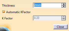
- Thickness
- KFactor: Ratio of the neutral axis to the material
thickness.
- Automatic KFactor. Select this check box to compute
the KFactor dynamically.
- Faces to ignore: The selected faces are considered as a
plugged holes when computing the unfold.
|
-
Click OK.
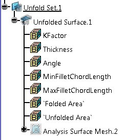
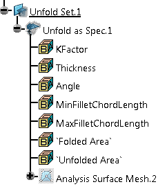
The unfold is created under an Unfold
Set.
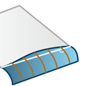
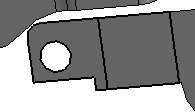
Initial model
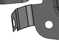
Result as Planar Surface
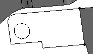
As
Partial Unfold
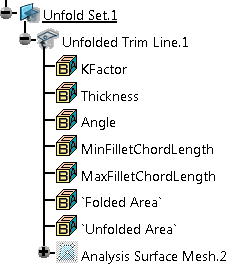
As Trim
Line
|