![]() |
This task shows you
how to place a contextual end cut.
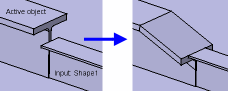
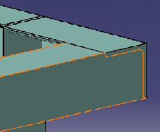
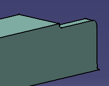
A contextual end cut is a feature with multiple inputs that depends on external objects, in our case, another shape, to be placed. |
||
![]() |
1. | Click
the Contextual Endcut
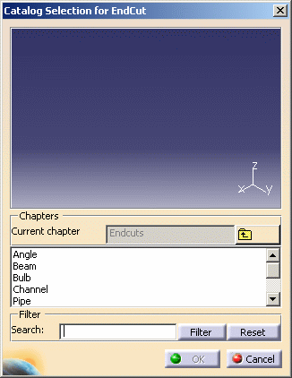
![]() The Catalog Selection for Endcut dialog box opens listing the various shape section types for which end cuts have been defined. |
|
![]() |
|||
2. | Double-click the Angle chapter, then Contextual Endcuts and select the end cut 'Getting_Started' in the lower part of the dialog box. | ||
The selected end cut is displayed in the preview. |
![]() |
||
3. | Click OK
to validate your selection. 
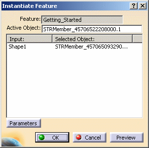
The Instantiate Feature dialog box opens. The Feature field lists the selected end cut. |
||
4. | Select the active
object, i.e. the shape on which the end cut will be placed.
|
![]() |
|
5. | Select the second shape from which information is obtained before placing the end cut. | ||
6. | Click OK
in the Instantiate Feature dialog box to place the end cut. 
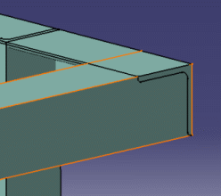
Note: The end cut is identified in the specification tree under the shape on which it is placed. |
||
![]() |
![]() |
||
7. | Place other end cuts as needed to connect the top four shapes. | ||
![]() |
|||
|