|
|
You can:
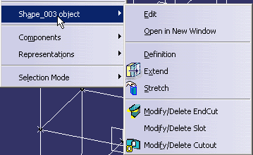
All modifications are done via the contextual menu on the shape
selected in the specification tree. |
|
|
|
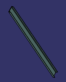
This task shows how to modify individual shapes. | |
|
|
No sample document is provided. | |
|
|
1. | To begin modifying a shape, first make the product active in the specification tree. Then, right-click the shape (in the specification tree) and select the type of modification you want to make from the contextual menu. |
 |
||
|
|
If you have created a large number of shapes, right-click the shape of interest in the geometry area, then select the Center Graph command to find your shape in the specification tree. | |
| 2. | You can modify several features of the shape, as described below. | |
|
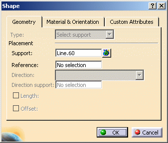
With the product active, right-click the shape and select Shape_xxx object and Definition. The Shape dialog box
displays. Alternatively, double-click the shape in the specification tree to activate it. Then, double-click to display the Shape dialog box.
Select the Geometry tab and make your changes. In the Geometry tab, you can change the method used to place a shape from Point to Point to Select Support, but not vice-versa. The Type field will always be grayed out. If your shape was placed using the Point to Point method, and you want to select a support, make the Support field active and select a support. The value in the Type field will change. Material & Orientation and Custom Attributes tabs, as needed. See Creating Shapes for more information about these tabs. You can also modify the shape orientation by using the manipulators in the design. For more information, see Using Section Manipulators. Click OK when done. |
||
| 3. |
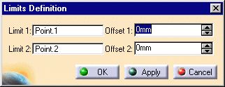
If you want to change the limits, then select Extend
in the drop down menu shown above. The Limits Definition dialog
box
appears.
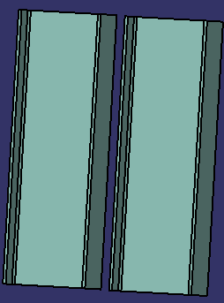
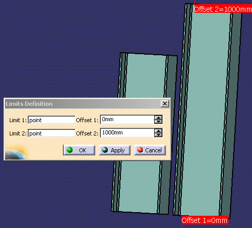
The images below show two shapes of the same size, and the result of the Extend operation.
|
|
|
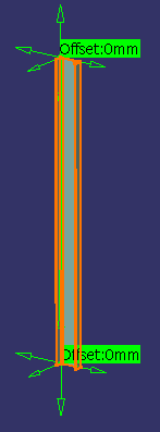
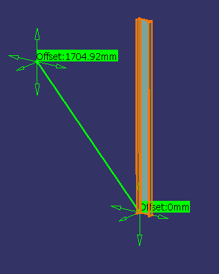
If you want to stretch the shape, then select Stretch
in the drop down menu. A graphic manipulator is
displayed letting you stretch the unconstrained linear shape along the
main axes of the section. Stretch your shape and click OK in
the Point Definition dialog box when done. Important: This command is only available for unconstrained shapes, i.e. those created by entering coordinates or with the Keep link with selected object option de-activated. The images below are: A section about to be stretched. The stretch maneuver performed on the section.
The result. |
||
|
||
|
|
||
