Parts need to be generated because in this application the components are essentially 2D objects, with the 3D dimensions defined as attributes. Using the command to generate parts creates CATParts from features, and these CATParts are used in downstream processes.
If the Piece Part Generator button is not visible you will need to change a setting. In the menu bar, click Tools - Customize, and click the Add Commands button. Find Piece Part Generator in the list, and drag it into your toolbar.
If you select All in Session then all systems in your session are selected, and all objects are available for generation. The Structure Piece Part Generator dialog box remains compressed, as shown in Step 1.
- Feature
Coping Options:
Plate Extrapolation Offset: Selecting this check box creates nibbling on plates with respect to connected objects. At seam position coping is deactivated by default.
For example in the following figure the gap of 5mm is introduced between two plates. This gap is introduced due to extrapolation offset given to the operating element to avoid confusion faces.
Once this check box is selected, extrapolation offset field becomes available. Default value for extrapolation offset value is 0mm.
Shape Web Extrapolation offset: Selecting this check box creates a nibbling on the web of a stiffener or stiffener on free edge with respect to the supporting plate.
For example in the following figure the gap of 5mm is introduced between plate and stiffener. This gap is introduced due to extrapolation offset given to the operating element to avoid confusion faces.
Once this check box is selected, extrapolation offset field becomes available. Default value for extrapolation offset value is 0mm.
Shape Extremities: Selecting this check box creates extrapolation on extremities of profile with respect to the limiting element.
Instantiate Slot from Catalog:
Plate: If you select this check box, a slot on the SDD plate is created as a slot feature. If you clear this check box, the slot is created as an opening feature, that is, a cutout on the resulting SR1 plate. This option is not applicable to a SFD plate. A slot on a SFD plate is always created as a slot in the resulting SR1 plate irrespective of your selection in this check box.
Member: If you select this check box, a slot on the SDD member is created as a slot feature. If you clear this check box, the slot is created as an opening feature, that is, a cutout on the resulting SR1 member. This option is not applicable to a SFD member. A slot on a SFD member is always created as a slot on the resulting SR1 member irrespective of your selection in this check box.
For example, in the first image given below, the Nibble and Slot options
are not selected. The slots are created as an opening feature in the
resulting piece part. In the second image, the Nibble and Slot options
are selected. The slots are created as a slot feature and the copings on
the bulkhead are also created.
| Nibble and Slot options not selected | Nibble and Slot options selected |
 |
 |
- Tree Structure
Keep Functional Volume Structure: Selecting this check box, maintains the structure of the functional volumes in your document. Functional volumes, and the objects within them, in your existing document will be replicated when the parts are generated. If you select As Product then a product will be created under the target for each functional volume in your document. If you select As Component then a component will be created under the target for each functional volume in your document.
Keep System Structure: If you select this check box, then the specifications tree structure of your original document will be maintained when the parts are generated, beneath the target that you selected. If you select As Product then a product will be created under the target for each system in your document. If you select As Component then a component will be created under the target for each system in your document.
Keep Object Structure: When you select this checkbox, you can choose to define your specifications tree structure as product or component. If you select As Product then all objects you create in the document will be shown at the same level. If you select As Component then the objects will be organized by the top level object, in this case deck. The images below show both selections.
After completion of piece part generation message is displayed and the More >> button gets activated.
The details of the objects are displayed in the Summary area, showing the SFD/SDD part name, SFD/SDD feature name, generated SR1 part name, status of the object and remarks.
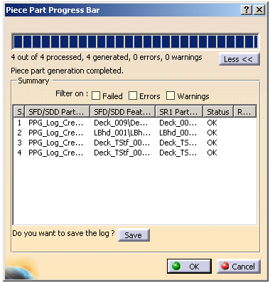
The status of the object can be OK or Failed.
If the object generation fails, the Remarks column provides the failure reason like ERROR/WARNING.
You can sort the displayed objects by applying one of the following filters:
- Failed: Shows the failed objects.
- Errors: Shows the objects which are having error
messages.
Note: You can use this option to view the objects with status OK but have errors. - Warnings: Shows the objects which are having warning messages.
Note: You can open this file in Microsoft Excel using tab as a delimiter.
- This command also works with Compartment and Access wall systems. However, for the part to be generated accurately, you must have the correct entry for the resource CompAccessPlateGenerationOptions (Compartment Access Plate Generation Options) in the project resource management file. See also List of PRM Resources and Flags.
- To view the weld information for the generated piece part, right-click and select xxx.1 object > Weld Information. The Weld Information dialog box appears displaying the weld face parameters.