Walls, cylindrical bends, conical bends and chamfers can be recognized. Hems are recognized as walls.
Recognize Features
You can recognize features such as walls, bend, stamps and edges for bends.
Open the required CATPart document containing a part created in the Part Design workbench.
-
Click Recognize
 .
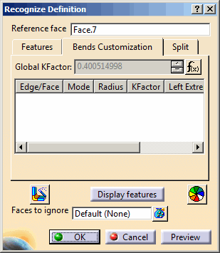
The Recognize Definition dialog box is displayed.
.
The Recognize Definition dialog box is displayed. 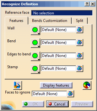
-
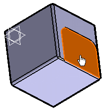
Select a reference face.

During the wall recognition process, you can also: - Choose the faces you do not want to be built, by selecting them manually after having activated the Faces to ignore field.
-
Select the recognition mode: Full
recognition
 ,
Partial recognition
,
Partial recognition
 or No recognition
 .
Full recognition is
selected by default. No recognition
is not available with walls.
.
Full recognition is
selected by default. No recognition
is not available with walls.

Click  to remove or
replace faces you previously selected.
to remove or
replace faces you previously selected. -
Click the feature's box to be recognized and select the features to keep in the 3D.
The number of features to be recognized appear in front of each box. -
To get a preview of the recognized features, click Display features.
It allows you to highlight them with the color defined by clicking Color selector .
.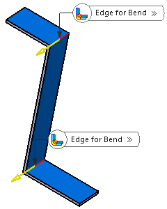
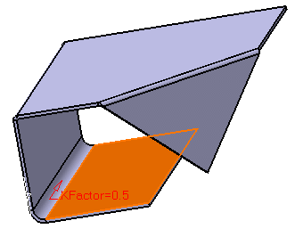
Note: A context menu is available on the label of the edge for bend to edit the radius, K-Factor, define the extremities, and swap extremities.
-
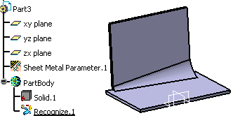
Click OK to validate.
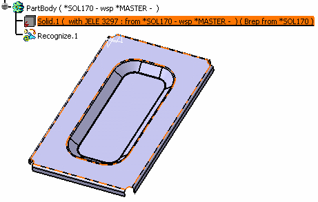
Features are generated from the Part Design geometry and the Recognize.x feature is added to the tree. At the same time, the Sheetmetal parameters are created, deduced from the shape geometry.
-
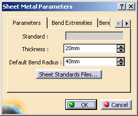
To modify the parameters, click Sheet Metal Parameters
 .
. 
-
You can modify the default bend radius and bend extremities parameters.
-
The thickness parameter cannot be modified because it is based, on the initial solid geometry, like the bend extremities and radius.
-
The bend allowance, being used to unfold the shape, and the bend corner relief affect all features, and therefore can be edited even for recognized features.
You can also define the sheet metal parameters prior to recognizing the part. In this case, you need to make sure that the Thickness parameter value corresponds to the part thickness. -
-
When all parameters have been redefined as needed, click OK in the Sheet Metal Parameters dialog box.
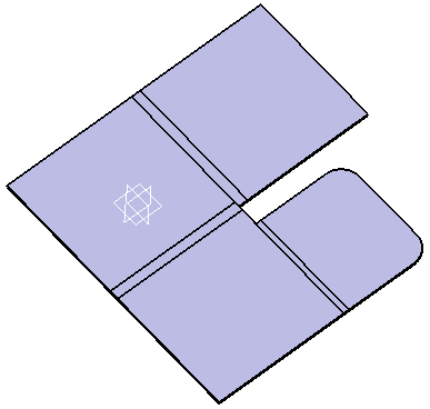
The solid is now a Generative Sheetmetal Design part. You can now deal with it as with any other Generative Sheetmetal Design part, adding Generative Sheetmetal Design features to complete the design, or unfolding it.
 |
 |
| Faces to select | Recognition result |
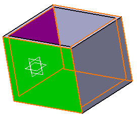
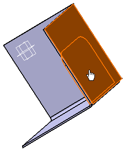
For example, if the initial part is a box such as shown below, you need to select two opposite inner faces, and outer faces on the other two sides of the box, in order to avoid overlapping when recognizing the walls.
In case faces are overlapping, you need to select the sides of each face. If you select only one face, the overlapping faces will be recognized as a unique pad and not as two independent walls.
 |
 |
|
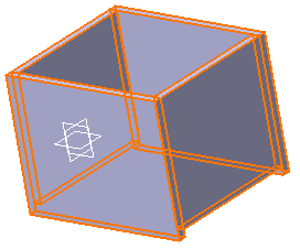
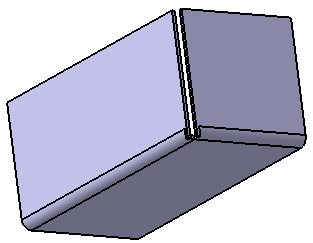
Face selected to be recognized as a wall |
Result of recognition when unfolding |
To avoid this, select first the inner side of the overlapping faces.
 |
Then select the outer side.
 |
The overlapping faces will be recognized as independent walls.
 |
Recognizing Stamping Features
Consequently, the following types of stamps can be recognized:
- Circular stamp
- Curve stamp
- Surface stamp
- Bead
- Bridge
- Louver
The recognize feature enables to create a Generative Sheetmetal Design stamping feature from a V4 model or parts created with Sheetmetal Design.
Open the required CATPart document containing a part created from a V4 model.
-
Click Recognize
.
The Recognize Definition dialog box is displayed. -
Select a reference face. It will be the reference face for unfolding and for the definition of the sheet metal parameters (i.e. all default parameters will be based on this face).
-
Click OK.
The stamps are generated from the geometry. 
- Three modes are available for the recognition :
-
The Full recognition and Partial recognition modes work the same way as in the wall.
-
The No recognition mode allows you to specify if you do not want stamps or bends to be recognized.
- There is no stiffening rib recognition, since the support feature for the stamp must be planar.
- Stamps containing inner contours such as flanged hole, flanged cutout cannot be recognized.
- Sharp stamps are not recognized.
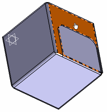
Recognize Chamfers
The chamfers are automatically recognized when you use the Recognize command.
|
 |
|
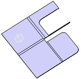
Folded view |
Unfolded view |
The chamfers with missing support faces as shown below cannot be recognized.
Recognize Conical Bends
The conical bends are automatically recognized when you use the Recognize command.
Manage the Bend Allowance
This task illustrates how to manage the bend allowance of the bends that will be recognized, to recreate a flat view.
Open the required CATPart document.
-
Click Recognize
.
The Recognize Definition dialog box is displayed. -
Select a reference face.
-
Click on the Bend Customization tab.
-
Select the bend edge or bend face you want to recognize.
Every feature on which you specify a K-Factor appears in the list. -
Specify the value of the Global K-Factor.

You cannot specify two different K-Factor values on the two faces of the same bend. -
Click OK.
Manage the Recognition of Complex Parts
-
Click Recognize
.
The Recognize Definition dialog box is displayed. -
Select a reference face.
-
Click on the Split tab.
-
Select the edge to be used for the split.
Tip: You can select an edge or a sketch.
It is displayed in the list along with the available split modes. -
Select the split mode:
- Split both
 : There will be no overlapping in the recognize result.
This is the default mode.
: There will be no overlapping in the recognize result.
This is the default mode. - Split first support
 : Only the first support is split.
 - Split second support
 : Only the second support is split.
 - No split
 : No split is performed so there might be an overlapping
in the recognize result.
: No split is performed so there might be an overlapping
in the recognize result. - Split with gap
 : You need to define a gap value to perform this split.
These options are also available when right-clicking the label that appears in the 3D.
- Split both
-
Click OK.
Result with bend recognition and first support split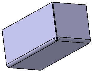
Result with bend recognition and defined gap
![]()