-
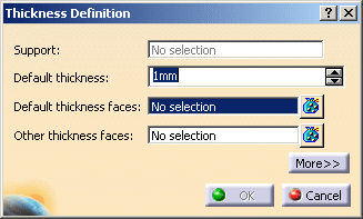
Click Thickness
 .
.
| The Thickness Definition dialog box opens. |
 |
-
Select the faces to thicken.
| The Support field is automatically filled with the support of the
selected faces and is grayed out. |
-
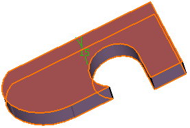
Enter a value. For instance, enter 15 mm.
| The faces become red and the application displays the thickness
value in the geometry. |
 |
-
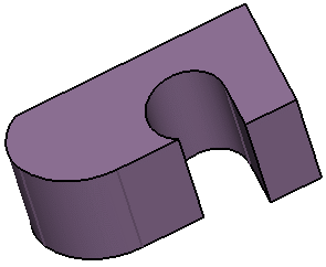
Click OK to thicken the part accordingly.
| The volume (identified as Thickness.xxx) is added to the
specification tree. |
 |
-
Double-click the thickness to edit it.
-
Click the Other thickness faces field and
select the lateral face as shown.
-
Double-click the thickness value displayed on this face.
-
In the Parameters Definition dialog box that appears,
enter 25mm.
-
Click OK to close the dialog box.
| The length between the selected face and the
resulting face is 25mm. |
-
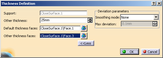
Click
More>>.
-
Select the
Smoothing mode under the Deviation
parameters section.
 |
There are
three
types of smoothing modes:
- None:
No smoothing is applied. This is the default option. The Max
deviation field is disabled.
-
Manual:
Allows you to enter a maximum deviation. The default value
is 0.1 mm.
-
Automatic:
Smoothing is applied automatically. The Max Deviation field is disabled.
|
-
Click OK to create the thickness feature.
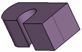 |
 |
The
multi-output capability is available. Click
 to display the list of
selected faces. to display the list of
selected faces. |
![]()