 |
-
Click Draft Angle
 from the Volume drafts sub-toolbar.
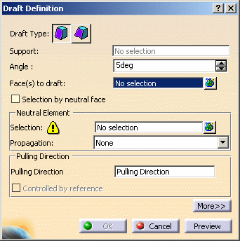
The Draft Definition dialog box is displayed and an
arrow appears on a plane, indicating the default pulling direction.
This dialog box displays the constant angle draft option as
activated. If you click the icon to the right, you then access the
command for creating variable angle drafts.
 |
-
Check Selection by neutral face to determine
the selection mode.
-
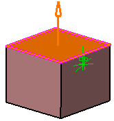
Select the upper face as the neutral element. This
selection allows the application to detect the face to be drafted.
| The neutral curve is displayed in pink. The faces to be drafted
are in dark red. |
The Support field is filled with the volume owning the
selected face.
 |
|
-
Set the Propagation option:
| |
- None: there is no propagation
- Smooth: the application integrates the faces
propagated in tangency onto the neutral face to define the
neutral element.
|
-
Define the Pulling Direction:
By default, it is normal to the neutral face and
is displayed on top of the part. The pulling direction is
displayed near the draft area to make it visible. As per the
inputs given for creating a draft, the pulling direction arrow
is located around the below elements in the given priority
order:
- Face as a neutral element
- Neutral curve
- Face or surface as a pulling direction
- Faces to draft
- Elements like axis, line, or plane as pulling direction
- Origin of a 3D part
|
|
 |
You can dock the pulling direction arrow on the top right
corner of the window. To do so, right-click the pulling
direction arrow and select Display indicator frozen on the
screen.
The same pulling direction that you specified for creating the
previous draft is used for the next draft. This pulling
direction based on the previously created draft appears only
when you define it explicitly in the previous draft and not
applied automatically due to the selection of the neutral
element. |
|
The Controlled by reference option is
now activated, meaning that whenever you will edit the element
defining the pulling direction, you will modify the draft
accordingly.
Note that when using the other selection mode (explicit
selection), the selected objects are displayed in dark pink. |
|
-
The default angle value is 5. Enter 7 degrees as the new
angle value.
| The application displays the new angle value in the
geometry. |
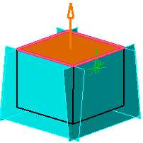
-
Click Preview to see the draft to be created.
It appears in light blue:
 |
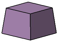
-
Click OK to confirm the operation.
The element (identified as Draft.xxx) is added to the
specification tree.
|
|
For further information about drafts, refer to
Creating Basic Drafts and Creating Drafts with Parting
Elements in Part Design documentation. |
|
|