|
-
Click Volume Revolve
 . .
| The Revolve Volume Definition
dialog box appears. |
-
Select the Profile.
 |
- The profile must be planar and closed or closed on the axis of
the sketch.
- There must be no intersection between the axis and the profile.
However, if the result is topologically consistent, the volume
will still be created.
- The profile must not be perpendicular to the revolution axis.
- If the profile is a sketch containing an axis, the latter is
selected by default as the revolution axis. You can select
another revolution axis simply by selecting a new line.
|
-
Select a line indicating the desired Revolution axis.
| It can be a line or the axis of a sketch. |
-
For Limit 1 and
Limit 2, specify the
limit types of the revolution.
Dimension: Enter angle values or use the graphic handles to define the
start and end limits of the revolving profile.
Up-to element: Select a geometric element. It can be
a point, a plane, or a surface. If a point is specified, the up-to
element is the plane normal to the revolution direction passing through
the given point.
In the angle box, enter a value to define an angular offset from the
selected up-to element.
Notes:
- The up-to element can intersect the profile and the
volume to be revolved. In the latter case, it must
completely cut the volume and there should not be any
partial intersections of the up-to element with the volume.
If you select two up-to elements, they must not cut each
other within the volume to be revolved.
- Wires cannot be selected as up-to element.
|
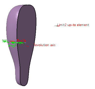
In the example, one side of the revolution volume
is limited by the point.
-
Click OK to create the volume.
| The volume (identified as Volume Revolve.xxx) is
added to the specification tree. |
 |
 |
Parameters can be edited in the 3D
geometry. To have further information, refer to
Editing Parameters. |
|