Chamfering is an operation of removing or adding
a flat section from a selected edge to create a beveled
surface between
the two original faces common to that edge.
Open the Chamfer1.CATPart document.
-
Click Chamfer
 in the Operations
toolbar.
in the Operations
toolbar.The Chamfer Definition dialog box appears.
-
In the Object(s) to chamfer box, select the edges to be chamfered.

- Chamfers can be created by selecting a face: the application chamfers its edges.
- The Support box automatically displays the feature to be
chamfered once the first
edge belonging to this feature is selected. It is always grayed out. Edges to be
added must belong to the same feature. Otherwise you need to remove the edges
first.
-
In the Mode list, select the desired mode:
-
Length1/Angle (default mode, i.e. intersection of the two perpendiculars of the normal lines): enter a
length value and an angle value. - Length1/Length2: enter two length values.
The Symmetric extent check box appears. Select it to define the same value for both lengths
(Length 2 is no longer available). - Chordal Length/Angle: enter a chordal length value
(i.e. the chamfer width) and an angle value.
Width = Length / cos(Angle) - Height/Angle: enter a height value (i.e. distance
between the intersection of the two adjacent faces
and the chamfer face) and an angle value.
Height = Length * sin (Angle)
-
-
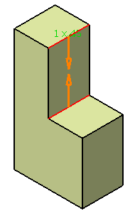
In the Length 1 box, enter the length value or use the arrows to change the value.
Here, we entered the length value as 5mm. -
In the Angle box, enter the value or use the arrows to change the value.
Here, we entered the angle value as 45deg. -
In the Extremities list, select any one of the below options:
- Smooth: a tangency constraint is imposed at the
connection between the chamfer and the support
surface, thus smoothing the connection. - Straight: no tangency constraint is imposed at
the connecting point between the chamfer and the
initial support, generating sometimes a sharp angle. - Maximum: the chamfer is limited by the longest selected edge.
- Minimum: the chamfer is limited by the shortest selected edge.
- Smooth: a tangency constraint is imposed at the
connection between the chamfer and the support
-
In the Propagation list, select the desired propagation mode:
- Minimal: Edges tangent to selected edges can
be taken into account to some extent. The application
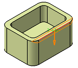
continues chamfering beyond the selected edge whenever it cannot do otherwise. Here, the chamfer
is computed on the selected edge only:
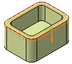
- Tangency: Chamfers the entire selected edge
as well as its tangent edges. It continues chamfering
beyond the selected edge until it encounters an edge that is non-continuous in tangency as shown
below:
- Minimal: Edges tangent to selected edges can
be taken into account to some extent. The application
-
Click Preview to see the chamfers to be created.
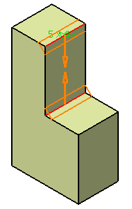
In our scenario, because both selected edges imply no tangencies, the choice of a propagation mode is unnecessary.
-
Select the Reverse check box to reverse the direction of the chamfer.
You can also click the blue arrow in the geometry. -
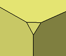
Select the Corner Cap check box to reshape the corner of the chamfered edges.
By default, this check box is selected.
-
Select the Trim Support check box to trim the support and assemble it to the chamfer.
By default, this check box is selected. -
Click OK to create the chamfers.
The element (identified as Chamfer.xxx) is added to the specification tree.
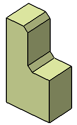
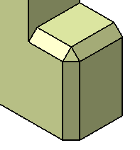
You can create a chamfer on the three concurrent edges by selecting a common vertex.
To do so,
- Right-click in the Chamfer corner(s) box and select Create by Edges or Vertex.
- Select a common vertex of the three concurrent edges and define the setback distance.
To access the Chamfer corner(s), click More>>.
Without Chamfer corner(s) With Chamfer corner(s) 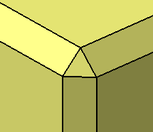
- Selection of a feature has high priority compared to selection of a sub-element. Thus, if you make changes at the feature level, sub-elements are affected accordingly.
- You can apply the edge intersection filter (which affects all the features in a model) in the User Selection Filter toolbar.
- The behavior of Propagation
box (which deals with sub-elements) in the
Chamfer Definition dialog box is dependent on the edge
selection filter in the following ways:
- If Tangent Intersection Edges (i.e. C1 mode) is selected, the Propagation box remains unavailable and displays Tangency.
- If Intersection Edges (i.e. C0 mode) is selected, the Propagation box remains unavailable and displays Intersection.
- If no mode is selected, a standard feature edge is created with the propagation of your choice. In this case, you can select either Tangency or Minimal in the Propagation list.
- When you edit an existing chamfer, the edge intersection filter automatically changes to a mode (C1 or C0), which was active at the time of chamfer creation. If you change the mode during edition, existing data is discarded. The chamfer cannot contain heterogeneous features.
- If you want to replace an existing edge, the new edge should be of the same propagation type. That is, if the edge is a C0 edge, the replace edge should also be a C0 edge. Similarly, for C1 edge, replace edge should be a C1 edge.
![]()