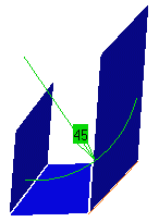
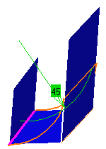
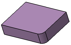
Edge fillets are useful to provide a transitional surface along a sharp internal edge of a surface.
This task shows how to create a constant radius fillet along the
internal edge of a joined surface.
The fillet surface is obtained by rolling a sphere over the selected edge.
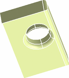
Open the EdgeFillet1.CATPart document.
-
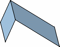
Click Edge Fillet
 .
.The Edge Fillet Definition dialog box appears. 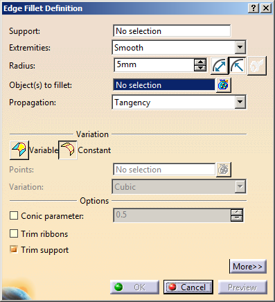
-
Select the edge to be filleted.
You can also select a face, provided there is no ambiguity as to the edge(s) to be filleted.
-
Use the combo to select the desired type of extremity for the fillet:
-
Straight: no tangency constraint is imposed at the connecting point between the fillet and the initial support, generating sometimes a sharp angle
- Smooth: a tangency constraint is imposed at the connection between the fillet surface and the support surfaces, thus smoothing the connection
- Maximum: the fillet surface is limited by the longest selected edge
- Minimum: the fillet surface is limited by the shortest selected edge
(Refer to Shape Fillets) -
-
Click the
 icon and enter the value of the fillet Radius.
A preview of the fillet appears. 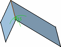
-
You can choose the Propagation type:
-
Tangency: the fillet is propagated up to the first edge that is not continuous in tangency.

The tangent continuous edges of the selected edge are included in the fillet to ensure better fillet stability and robustness (More fillets are automatically rerouted in case of design changes). -
Minimal: the fillet is propagated up to the first geometric limitation.
-
Intersection: the fillet is propagated to all the edges that have been generated by intersecting the features.
-
-
Click Constant
 as a variation type.
 -
Select the Conic parameter check box. This check box allows you to vary the section of the fillet.
For a parameter comprised between or equal to: - 0.5, the resulting curve is a parabola.
- 0 < parameter < 0.5, the resulting curve is an arc of an ellipse
- 0.5 < parameter < 1, the resulting curve is a hyperbola.

- Conical fillets do not handle twist configurations. If a twist is detected, the fillet operation fails.
- Conical fillets may produce internal sharp edges. However, healing is used to smooth these sharp edges. Refer to Healing Geometry for more information.
- If the fillet surface curvature is lower than the support curvature, fillet surface relimitation may fail. In such cases, the conic parameter has to be decreased.
-
You can check Trim support to relimit the support elements and assemble them to the fillet.
-
Optional: Select the Tracks creation check box to create permanent features for the tracks of the edge fillet ribbons.
These two tracks remain at the same position with respect to the support face. -
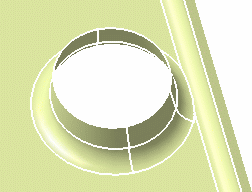
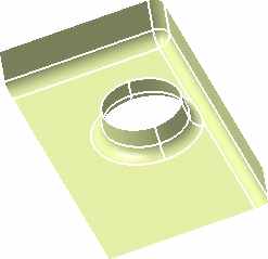
Click OK to create the fillet surface.
The surface (identified as EdgeFillet.xxx) is added to the specification tree. 
- Note that
the selection of the feature prevails over the selection of the
sub-element.
To select a sub-element, you need to apply the ''Geometrical Element'' filter in the User Selection Filter toolbar.
For further information, refer to Selecting Using A Filter in CATIA Infrastructure User's Guide. - While editing the edge fillets created by selecting Tangent intersection edges in Intersection mode, a warning message appears. It states that only edges resulting from intersecting features can selected in the intersection mode.
- You can apply the edge intersection filter (which affects all the features in a model) in the User Selection Filter toolbar.
- The behavior of Propagation box (which deals with
sub-elements) in the Edge Fillet Definition dialog
box is dependent on the edge selection filter in the following
ways:
- If Tangent Intersection Edges (i.e. C1 mode) is selected, the Propagation box remains unavailable and displays Tangency.
- If Intersection Edges (i.e. C0 mode) is selected, the Propagation box remains unavailable and displays Intersection.
- If no mode is selected, a standard feature edge is created with the propagation of your choice. In this case, you can select either Tangency or Minimal in the Propagation list.
- When you edit an existing edge fillet, the edge intersection filter automatically changes to a mode (C1 or C0), which was active at the time of edge fillet creation. If you change the mode during edition, existing data is discarded. The edge fillet cannot contain heterogeneous features.
- If you want to replace an existing edge, the new edge should be of the same propagation type. That is, if the edge is a C0 edge, the replace edge should also be a C0 edge. Similarly, for C1 edge, replace edge should be a C1 edge.
- Note that
the selection of the feature prevails over the selection of the
sub-element.
Keeping Edges
If you have difficulties selecting the edge, use the up/down arrows to display the preselection navigator.
If the Conic parameter check box is selected, the Edge(s) to keep field is grayed out. Conversely, if the Edge(s) to keep field is selected, the Conic parameter check box is disabled.
If an Error Message is Issued...
In case you have specified no edges you want to exclude from the fillet operation, the application may sometimes detect that some edges cause trouble during the fillet computation. The application then issues an error message asking you if you wish to select the edges you do not want to fillet.
There are two ways of specifying the edges you want to keep:
- By explicitly specifying these edges
This means that you need to click Yes in the Feature Definition Error dialog box. Then you just need to click the Edit button from the Update Diagnosis dialog box that appears, click the Edges to keep field from the Edge Fillet dialog box and select the edge in the geometry. The application then displays the selected edge in pink meaning that the edge will not be affected by the fillet operation. The fillet is eventually computed and does not affect the "keep" edge. - By letting the application find a solution
If you do not wish to explicitly select the edge you do not want to fillet, just click No in the Feature Definition Error dialog box. The application then tries to find a solution.
Both methods may not give the same result depending on the geometry. If you prefer to let the application find a solution, the application finds an appropriate physical edge in the geometry, then considers it as the edge to be kept. If no edge can be found, then it finds a solution by itself.
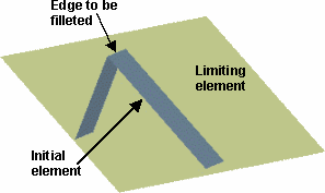
Limiting Fillets
-
Once the edge to be filleted has been selected, and the radius keyed in, click Preview then More>>.
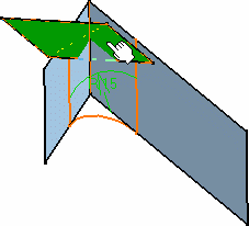
-
Click in the Limiting element(s) field, then select the trimming element(s).
These elements can either be surfaces, planes, or points on edges. An arrow indicates which portion of the fillet is to be retained. 
- You can use one or more limiting elements.
- You can define a limiting element just by clicking a point on one of the selected edges to be filleted.
-
Click on this arrow to inverse it, if needed, to retain the opposite side of the fillet.
-
Click OK to create the limited fillet.
In the illustration, the limiting surface has been hidden. 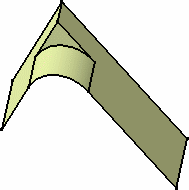
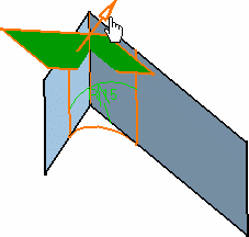
You can create limiting elements just by clicking on the edge to be filleted. The application displays this element as a blue disk. 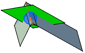
- You can select planes or points as limiting elements. Points must be located on the edge to be filleted and they must have been created using the On curve point type available in the Point Definition dialog box.
- Make sure the limiting
element is not larger than the initial element, as illustrated
here. If so, decrease the size of the limiting element as prompted
by the warning message.
Ignoring Edges
Trimming Overlapping Fillets
they overlapping.
![]()
-
Click Edge Fillet
and select the edges at the base of the
cylinder and the one along the vertical surface.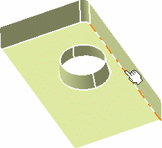
-
Click Preview.
The two fillets clearly overlap. 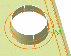
-
In the Edge Fillet Definition dialog box, check Trim ribbons and click OK.
Note that Trim ribbons is available with the Tangency and Intersection edges propagation mode: - In Minimal mode, Trim ribbons is grayed,
as it is implicitly active. The results would be trimmed fillets,
and no propagation.
- In Tangency mode, with Trim ribbons
deselected, the fillets intersect, with no trimming, and the
propagation
is performed.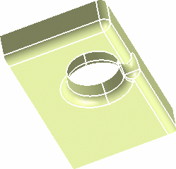
- In Tangency mode, with Trim ribbons
checked, the fillets are trimmed and the propagation is performed.
- In Minimal mode, Trim ribbons is grayed,
as it is implicitly active. The results would be trimmed fillets,
and no propagation.
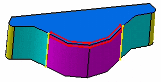
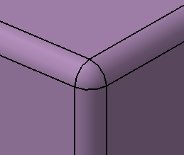
Filleting Volumes
![]()
-
Click Edge Fillet
.The Edge Fillet Definition dialog box appears. -
Select the edge to be filleted.
-
Set the Radius to 10mm.
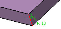
-
Click OK to create the fillet volume.
Extremities and Trim support are grayed out. They cannot be used with volumes.
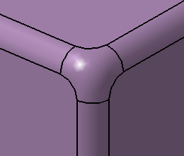
To access the Blend corner(s), click More>>.
Right-click in the Blend corner(s)
box and select Create by edges or vertex.
The resulting edge fillets are created by edges.
| Without Blend corner(s) | With Blend corner(s) |
 |
 |
The edition of an edge fillet sometimes generates an update error