Following topics are discussed:
Face Pair Selection
- Offset ratio is relative to the ordering of faces and the
mid-surface is created at an offset from the selected face.

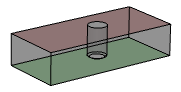
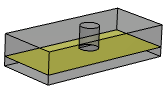
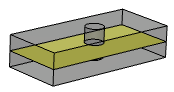
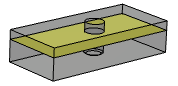
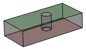
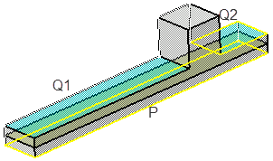
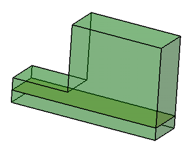
For illustration purpose, main side is color coded as red and the other side as green in the following images.
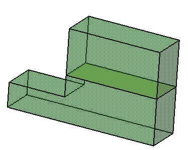
| Face Pair | Mid Surface with Offset ratio=0.7 | Offset ratio=0.5 | Offset ratio=0.3 |
 |
 |
 |
 |
 |
|
|
|
- The shape of the mid-surface depends on the order of face selection.
- For face pairs P1-Q and P2-Q, the mid-surface is
non-continuous.
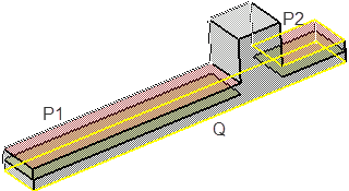
- For face pairs P-Q1 and P-Q2, the mid-surface is
continuous.
- For face pairs P1-Q and P2-Q, the mid-surface is
non-continuous.
|
|
A face can belong to more than one pair. |
Multi-cell Management
Contextual Edition
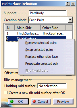
- Select Replace other side face to replace the second face of the pair with the first one.
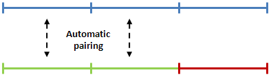
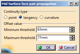
- Select Propagate selected pair to automatically create a pair of
adjacent faces by propagation.
- The face pair is propagated radially according to
the continuity criterion. A pair is kept if its offset
value is within the specified threshold.
- In some cases, propagation might be done on the other side of the selected volume, resulting in swapping of some face pairs. You will need to swap back these pairs manually.
- The face pair is propagated radially according to
the continuity criterion. A pair is kept if its offset
value is within the specified threshold.
- Select Find invalid pairs to find and select existing face pairs
that are invalid for mid-surface creation, such as:
- Pairs whose input topology is not part of the selected input support
- Incomplete pairs
- Pairs with input face in error (lost B-REP)
- Duplicate pairs
- Pairs whose input faces are not offset from each other.
|
|
The Find invalid pairs option is available only when the feature is in error. |
|
|
All of the contextual selection and edition options are also available in the 3D area. You can right-click the face pair to select these options. |
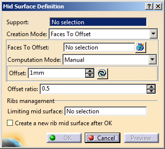
Create a Mid Surface
-
Click Mid Surface
 in the Surfaces toolbar (Offsets sub
toolbar).
in the Surfaces toolbar (Offsets sub
toolbar). The Mid Surface Definition dialog box appears. 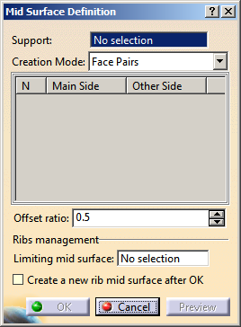
-
In the Support box, select the solid feature, volume feature or body that contains a pair of faces.
-
In the Creation Mode list, select Faces Pairs and select one or more pairs of faces from which the mid-surface will be extracted.
-

The Face Pairs area becomes available only after you select a feature in the Support box. 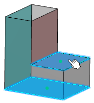
In the Offset ratio box, type the offset value or use the arrows to change the value.
The value of the offset ratio should be between 0 and 1. 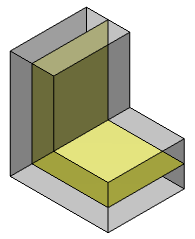
-
Click OK to generate the mid-surface.
The created mid surface is automatically extrapolated and relimited to the selected support.
- Click Mid Surface
in the Surfaces
toolbar.
The Mid Surface Definition dialog box appears.
- In the Support box, select a solid feature, volume feature or a body.
- In the Creation Mode list, select Faces to Offset.
- In the Faces To Offset box, select either the faces to offset or the
extract features, as required.
- Face selection: Select one or more faces in the work
area.
Note: You can click to see a list of selected faces. You can then click Replace or Remove to modify the list, if needed. - Extract feature selection: Perform one of the following actions from the context menu:
- Select Insert > Operations > Extract. The Extract Definition dialog box appears. For more information, refer to Extracting Geometry.
- Select Insert > Operations > Multiple Extract. For more information, refer to Extracting Sub-Elements.
- Face selection: Select one or more faces in the work
area.
|
|
|
- In the Computation Mode list, select Manual.
- Click Compute Offset beside the
Offset box.
- Offset faces from the selected faces are detected.
- Minimum and maximum offset values are computed and
displayed in the work area with the
Min and
Max
indicators.
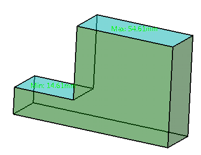
- Average offset value is computed and displayed in the Offset box.
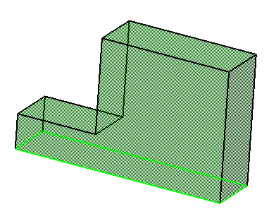
- Optional: Click
Min or Max indicator in the work area to
evaluate the offset parameter.
The value in the Offset box is refreshed accordingly. - Optional: Right-click
Min or
Max indicator in the work area and
select Remove Min or
Remove Max, respectively from the context menu.
The Min or Max indicators are removed from the current face. They re-appear on the next sequential face with the recomputed Min or Max value.
Note: The indicators do not appear after they are removed from the last face. - In the Offset ratio box, type the offset value or use the arrows
to change the value.
Note: Value of offset ratio must be between 0 and 1. - Click OK.
The mid surface is generated. 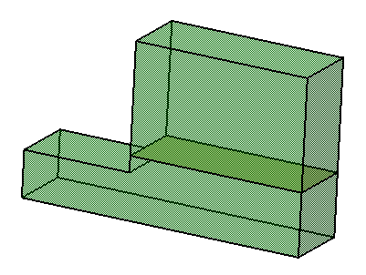
You can create a mid surface from a set of faces (or extract features) and an associative offset.
|
- In the Support box, select a solid feature, volume feature or a body.
- In the Creation Mode list, select Automatic.
- Clear the Automatic Thickness Threshold
check box and specify a Thickness Threshold. This length parameter acts as maximum
distance for the selection of pairs of faces to create the mid surface.
You can select the Automatic Thickness Threshold check box to automatically compute the thickness threshold. The computed value appears in the Thickness Threshold field. - Click OK.
The mid surface is generated. 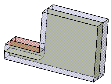
- Vary the Thickness Threshold and click OK.
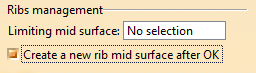
Manage Ribs
Perform above steps 1 to 4 to define the main shell mid-surface.
The Mid Surface Definition dialog box appears. Select the Create a new rib mid surface after OK check box.
Click OK.
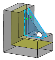
The Mid Surface Definition dialog box appears again with Limiting mid surface box containing the main shell mid-surface. In the Face Pairs area, select a pair of faces from the rib.
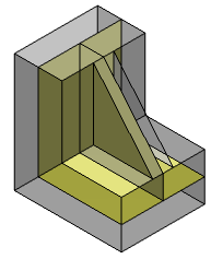
During the mid-surface creation of ribs, offset ratio is set to 0.5 by default. Click OK .
The rib mid-surface is generated with the main shell mid-surface acting as a relimiter.