 |
This command is only available with the Generative Shape Optimizer
product. |
 |
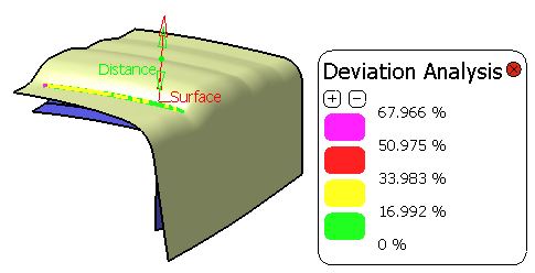
This task shows you how to create a rough offset surface, that is a
constant offset surface which approximates the initial surface to keep only
its main characteristics. |
 |
Open the RoughOffset1.CATPart
document. |
 |
-
Click Rough Offset
 . .
| The Rough Offset Surface Definition dialog box appears. |
") |
-
Select the Surface to be offset.
| An arrow indicates the proposed direction for the offset. Click
it to reverse the direction. |
-
Specify 20mm as the Offset value.
-
Set the approximation tolerance by specifying a value as the
Deviation value.
The default value is 1mm.
|
-
Click Preview
to preview the offset surface.
| The offset surface is displayed normal to the reference surface.
|
") |
|
A progress bar is displayed to allow the control of
the computation. |
")
|
-
-
Click OK to create the surface.
| The surface (identified as Offset.xxx) is added to the
specification tree. |
") |
| Note that the boundaries of the rough offset
surface are not computed. Only a global boundary that contains one
sub-element is created. |
- You can display the offset surface on the other side of the
reference surface by clicking either the arrow or Reverse
Direction.
- You can generate two offset surfaces, one on each side of the
reference surface, by checking Both sides.
|
|
|
|
Note: If you are a DS Passport customer, you can read the QA00000018192
article from the Knowledge Base for more about rough offset surface.
|
|
|
In case an error message is issued
asking you to modify the inputs, we advise you to change the deviation,
either by increasing or decreasing it.
|
|
 |
")
")