This task shows how to create fill surfaces between a number of boundary segments.
Open the Fill1.CATPart document.
-
Click Fill
 in the Surfaces toolbar.
The Fill Surface Definition dialog box appears.
-
In the Outer Boundaries tab, select curves or surface edges to form the outer closed boundary.
A diagnosis is displayed in the 3D area and the fill surface is previewed within the boundary.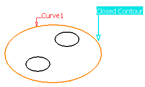

You can also create a fill surface without selecting the outer boundaries, if the Generative Shape Optimiser product is available. You can select any one of the following: - Inner boundaries
- Inner boundaries and passing elements
- Passing elements (at least three non-collinear points or a curve).
-
If needed, in the Inner Boundaries tab, select inner curves or surface edges to form the inner closed boundary.
Note:
Only curves corresponding to a single inner boundary are displayed in the list.- Only curves corresponding to a single inner boundary are displayed in the list.
- The Inner Boundaries tab is available with Generative Shape Design or Generative Shape Optimiser product.
A diagnosis is displayed in the 3D area and the fill surface is displayed within the boundary.
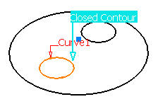
The resulting surface will be a fill surface between the outer and inner closed boundaries.
You can switch from the Outer Boundaries and Inner Boundaries tabs during the selection, however, the diagnosis
is displayed only for the curves corresponding to the active tab. -
If needed, click Add New Boundary to add a new boundaries or Remove Current Boundary to remove the selected boundary.
If you click Add New Boundary, the currently displayed curve is cleared in the list to let select another curve. -
If needed, click Previous or Next buttons to navigate between all inner curves and their supports defining a closed contour.
When the current boundary is the last one, the Next button is unavailable. Similarly, when it is the first one, the
Previous button is unavailable. You can use the spinners to move from one set of curves to another or directly click a number in the box. -
For both tabs, you can select a support surface for each curve or edge. In this case, the continuity will be assured between the fill surface and selected support surfaces.
You can define a support just after the selection of the curve or by clicking the curve in the list and selecting a support. To be able to select a support, the boundary must fully lie on the support. -
For both tabs, you can select a continuity type for each support surface. In the Continuity list, select the type of continuity between the selected support surfaces and the fill surface.
The following types of continuity are available:- Point
- Tangent, or
- Curvature continuity.
-
You can edit outer and inner boundaries by first selecting an element in the dialog box list then clicking a button to either:
-
Add a new element after or before the selected one
-
Remove the selected element
-
Replace the selected element by another curve
-
Replace the selected support element by another support surface
-
Remove the selected support element.
Inner and outer boundaries cannot intersect, be merged or be the same. -
-
Click in the Passing element(s) box, and select one or more points and curves.
This element can either be a point or a curve through which the filling surface must pass, thus adding a constraint to its creation. However, you may need to alleviate the number of constraints by removing the supports. 
The passing element(s) should lie within the area delimited by the selected curves. If not, the results may be inconsistent. -
You can select Planar Boundary Only to fill only planar boundaries, when the boundary is defined by one curve on one surface.
-
Define the Deviation mode to specify the gap between the fill surface and the boundaries.
- None: Default resolution value. The tolerance is deactivated.
- Automatic: Deviation of 100 times the resolution.
- Manual: Deviation manually defined in the box.
In the Tools > Options > Shape > Generative Shape Design > General tab, - If the Continuity Type is either Tangency or Curvature, the deviation is set to Manual.
- The Maximum deviation value is taken as the default deviation value for the fill.
The curves should be selected so that there should not be a gap superior to 0.1mm between them. Otherwise,
an error message is issued. If the gap between the two contours is greater than the maximum deviation, the gap is not filled, and the resulting surface still displays a gap. -
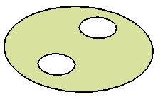
Click OK to create the fill surface.

Detecting the Canonical Portion
The Canonical portion detection check box
automatically computes the cylindrical surfaces information,
if they exist in the fill surface.
Note: Planar surface is unaffected by the selection of Canonical portion detection
check box as it is already a canonical surface.
By default, this option is selected.
Particular Cases
-
The selected curves or surface edges can intersect. Therefore a relimitation of the intersecting boundaries is performed to allow the creation of the fill surface.
-
Two consecutive boundaries must have only one intersection.
-
The selected curves cannot be closed curves.
-
-
The selected curves or surfaces edges can have non-coincident boundaries. Therefore, an extrapolation is performed to allow the creation of the fill surface.
The distance between non-coincident boundaries must be smaller than 0.1mm. 
-
A two-side fill surface cannot be created in the following ambiguous cases:
-
one intersection and two distances below 0.1 mm
-
no true intersection (therefore there may be several distances below 0.1 mm)
-
Check if the fill creation required a trim
![]()