It can be any type of surface, including multi-patch surfaces resulting from fill or any other operation.
-
Click Offset
 .
.The Offset Surface Definition dialog box appears. -
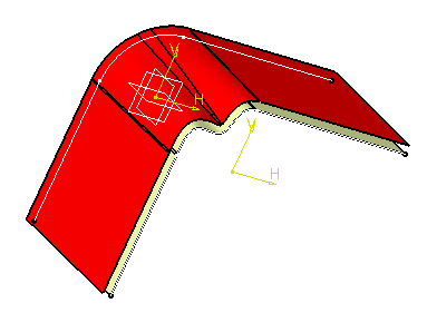
Select the Surface to be offset.
An arrow indicates the proposed direction for the offset. -
Specify 200mm as the Offset value.
-
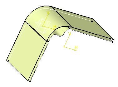
Click Preview to preview the offset surface.
The offset surface is displayed normal to the reference surface. 
-
Click OK to create the surface.
The surface (identified as Offset.xxx) is added to the specification tree. 
- Depending on the geometry configuration and the offset value, an offset may not be allowed as it would result in a debased geometry. In this case, you need to decrease the offset value or modify the initial geometry.
- When you modify an input value through the dialog box, such as the offset value or the direction, the result is computed only when you click Preview or OK.
- Parameters can be edited in the 3D geometry. To have further information, refer to the Editing Parameters chapter.
Setting Optional Parameters
- You can display the offset surface on the other side of the
reference surface by clicking either the arrow or the Reverse
Direction
button.
- You can define a smoothing type on the offset surface:
- None: the smoothing is constant. This is the default type.
- Automatic (you can use the
Offset3.CATPart
document): a local smoothing is applied only if the constant offset
cannot be performed. It cleans the geometry of the surface and
enables the offset.
A warning box is launched and the modified surface is shown in the 3D geometry.
If a surface still cannot be offset, no smoothing is performed and a warning message is issued (as in the constant offset mode). If you click Yes, erroneous sub-elements are removed and the offset operation goes on. - Manual: a local smoothing is
applied as in the Automatic type. You need to define a Maximum
Deviation below which the elements are to be offset. If the
resulting deviation is greater than the defined deviation, no
smoothing
is performed and a warning message is issued (as in the constant offset
mode). If you click Yes, erroneous sub-elements are
removed and the offset operation goes on.
- The deviation should be comprised between 0.001mm and the Offset value (-0.1mm). For instance, if the Offset value is 20mm, the maximum deviation is 19.9mm.
- The Maximum Deviation field is only available with the Manual smoothing type.
- You can select the Regularization type on the
offset surface:
- Local: The
Local regularization option regularizes the offset
surface by adding local modifications to the offset
surface. Therefore, using this option, the deviation between the
offset surface and the surface to be offset is
minimized. This option improves the robustness of the
offset computation.
- Global: The Global
regularization option regularizes the offset surface
completely. The same deviation is applied everywhere. If
the local regularization fails, by default, the offset
surface is globally regularized.
The Regularization option is available only with Automatic and Manual smoothing type.
- Local: The
Local regularization option regularizes the offset
surface by adding local modifications to the offset
surface. Therefore, using this option, the deviation between the
offset surface and the surface to be offset is
minimized. This option improves the robustness of the
offset computation.
- generate two offset surfaces, one on each side of the reference
surface, by checking the Both sides option.
- create several offset surfaces, each separated from the initial surface by a multiple of the offset value, by checking the Repeat object after OK option.

- Would the value be inconsistent with the selected geometry, a warning
message is displayed, along with a warning sign onto the geometry.
If you move the pointer over this sign, a longer message is displayed to help you continue with the operation. Furthermore, the manipulator is locked, and you need to modify the value within the dialog box and click Preview. 
Removing Sub-Elements
The Sub-Elements to remove tab helps you for the analysis in case the offset encounters a problem.
Open the Offset2.CATPart document.
-
Perform steps 1 to 3.
-
Click Preview.
-
Click Yes to accept the offset.
In the Offset Surface Definition dialog box, the Sub-Elements to remove tab lists the erroneous sub-elements and a preview of the offset is displayed. 
Important:
- This list is stable at update but not always when you create a new offset. As a consequence, the erroneous sub-elements in the list may be different.

-
If you move the mouse over a flag note, a longer message giving an accurate diagnosis is displayed.
-
You can remove a sub-element by right-clicking it and choosing Clear Selection from the contextual menu.
As this list is not always optimal, you can manually add or remove sub-elements:- Add Mode:
- when you click an unlisted element in the geometry, it is added to the list
- when you click a listed element, it remains in the list.
- Remove Mode:
- when you click an unlisted element in the geometry, the list is unchanged
- when you click a listed element, it is removed from the list
If you double-click Add Mode or Remove Mode, the chosen mode is permanent, i.e. successively selecting elements will add/remove them. However, if you click only once, only the next selected element is added or removed. You only have to click the button again, or click another one, to deactivate the mode. 
The list of sub-elements to remove is updated each time an element is added.
Note that if you modify an input in the Offset dialog box, the list is re-initialized. However, this list is not re-initialized if the offset parameter is modified directly from the tree by double-clicking Offset under Offset.xxx. This means that you will have to reselect the surfaces under the Sub-Elements to remove tab.
The availability of context commands depend on the location where you activate the contextual menu, and the context commands act only on the lines that you right-click. If more than one lines are highlighted, right-clicking one highlighted line is equivalent to right-clicking all the highlighted lines at the same time. In this case, the context command acts on all the highlighted lines. Consider the following cases:
Case 1: line 1 is highlighted and line 1 is right-clicked: the selected contextual command will act on line.
Case 2: line 1 is highlighted and line 2 is right-clicked (but not highlighted): the selected contextual command will act on line 2.
Case 3: line 1 and line 2 are highlighted and line 1 is right-clicked: the selected contextual command will act on both line 1 and line 2.
Case 4: line 1 and line 2 are highlighted and line 3 is right-clicked (but not highlighted): the selected contextual command will act on line 3.
You can select the Automatically Computes Sub-elements To Remove check box to automatically compute and remove sub-elements. Use this check box to obtain a better result after a modification of the offset parameter of the offset feature.
In this case, the Sub-elements to remove list is not available for manually adding or removing the sub-elements. -
Click Preview.
The offset surface is displayed normal to the reference surface. -
Click OK to create the surfaces.
The surfaces (identified as Offset.xxx) are added to the specification tree. 
Performing a Temporary Analysis
-
Perform steps 1 to 3 (set 20mm as the Offset value).
-
Click Preview.
The Temporary Analysis icon is available from the Tools toolbar. -
Click Temporary Analysis mode
 .
. -
Select the analysis to be performed in the Analysis toolbar by clicking either Connect checker
 or Surfacic Curvature Analysis
 .
. -
Click OK in the Connect checker or Surfacic Curvature Analysis dialog box.
You must activate the temporary analysis mode before running any analysis. Otherwise, a persistent analysis will be performed.
The Temporary Analysis node is displayed in the specification tree and the associated analysis (here, Surfacic Curvature Analysis.1) appears below:
- The analysis is not persistent. Thus when you click OK in the Offset Surface Definition dialog box to create the curve, the Temporary Analysis node disappears from the specification tree.
- An option is available from Tools > Options to let you automatically set the analysis as temporary. Refer to the Customizing section.
![]()