|
This command is only available with the
Automotive Body in White Templates product. |
 |
This task shows you how to:
|
|
|
Create a Blend Corner Using the Point Creation Mode
|
 |
Open the
BlendCorner.CATPart document. |
 |
-
Click Blend Corner
 in the BiW
Templates toolbar. in the BiW
Templates toolbar.
| The Blend Corner Definition dialog box
appears. |
-
From the Creation Mode
list, select Point.
-
Select two or more faces.
 |
- All the selected faces must belong to the same global
support.
- The Global support box is automatically
filled by the surface belonging to the selected faces.
|
-
Click Preview.
-
From the Sections list, you can:
- remove the selected section.
- replace the selected section with another section.
- reverse the orientation of the selected section.
|
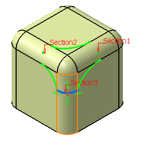
-
Move the manipulator arrows to edit the point on the
surface.
-
Click Invert sew result to inverse the
orientation of the blend corner.
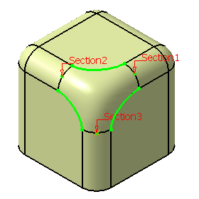
-
Click OK to create the blend corner.
The element (identified as
Blend Corner.xxx) is added to the specification
tree.
|
|
|
Create a Blend Corner Using the Setback Creation Mode
|
|
|
Open the
BlendCorner.CATPart document. |
|
|
-
Click Blend Corner
in the
BiW
Templates toolbar.
-
From the Creation Mode list, select Setback.
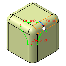
-
Select two or more faces.
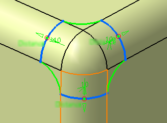
The selected fillet faces appears in the Sections list with
default setback values.
|
|
- All the selected faces must belong to the same global
support.
- The Global support box is automatically
filled by the surface belonging to the selected faces.
|
-
From the Sections list, you can:
- remove the selected section.
- replace the selected section with another section.
- reverse the orientation of the selected section.
- change the setback values for individual faces using the
Setback box. You can click Apply to all
if you want to apply the same setback value to all faces.
You can also use the manipulators in the 3D to change the
setback values.
|
-
Click Invert sew result to inverse the
orientation of the blend corner.
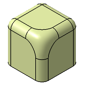
-
Click OK to create the blend corner.
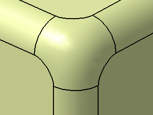
The element (identified as
Blend Corner.xxx) is added to the specification tree with
setback parameters under it.
|
|
 |