|
This command is only available with the
Automotive Body in White Templates product. |
 |
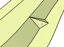
This task shows how to create a
bead, in order to add strength to a part.
The created bead shape is a triangle shape. |
 |
Open the Bead1.CATPart document. |
 |
-
Click Bead
 in the BiW Templates toolbar.
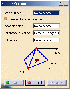
| The Bead Definition dialog box is displayed. |
 |
-
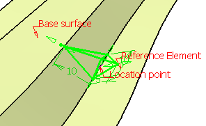
Select the Base surface.
|
|
The base surface must have at
least one internal sharp edge. |
 |
Check Base surface relimitation to trim the base
surface with the bead shape. |
-
Select a point on the sharp edge.
-
Define a Reference direction.
| By default, it is the tangent direction to the location edge at
the location point. |
|
The
Reference Element is updated. |
|
|
- The
Reference Element
maintains the orientation of the bead, if the location point of
the bead changes from one edge to an adjacent edge.
- You can also
right-click the Reference Element field and
select the following items from the contextual menu:
- Clear
Selection: if you do not want to specify any
reference element.
- Default Selection:
if you want to select the default element.
|
-
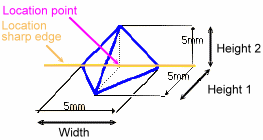
Define the bead parameters by clicking the value to edit
in the dialog box or by clicking the manipulators in the 3D geometry.
|
|
|
|
These values must be positive. |
 |
-
Click Preview.
-
Click OK to create the bead.
 |
 |
|
 |
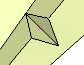
| With Base surface relimitation |
|
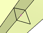
Without Base surface relimitation |
|
|
 |