|
-
Click Mating Flange
 . .
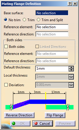
| The Mating Flange Definition dialog box is displayed. |
 |
-
Select the Base surface.
It can have several faces and internal sharp edges.
-
Select a Reference element to position the
mating flange on the base surface.
|
It can be:
-
a plane or
a surface.
The reference location is computed as an intersection with the base
surface.
-
a curve (as
in our scenario): the curve can be either a 3D curve or a planar
curve and must have a projection on the base surface along the
reference direction.
 |
We
advise you not to use the intersection or projection curve but
rather the input surface or curve. |
|
-
Select a Reference direction.
The reference location is a curve computed as a projection along the
direction.
 |
-
To
select a default reference direction, right-click in the field and
choose the Default Selection contextual item.
Conversely, to clear the selection, right-click in the field and
choose the Clear Selection contextual item.
-
If a
direction is selected, both Default Selection and Clear
Selection items are available from the contextual menu.
-
If a plane
or a surface is selected as a
Reference element then
Reference direction field will be disabled, as
reference location is computed as an intersection of that plane
with base surface. In this case OK
and Preview are
available.
|
|
|
The intersection or the projection curve must be
long enough to join the base surface boundaries. |
 |
| The mating flange reference
location feature is created in hidden mode and is temporarily shown
during edition. |
-
Define the mating flange parameters by clicking the value
to edit in the dialog box or by clicking the manipulators in the 3D
geometry.
-
Click Preview.
-
Define the thickness:
-
Default thickness: is generally the part
thickness and is used as the default offset value. You can define
its value either by entering a value in the field or using the
manipulators in the 3D geometry.
-
Local thickness:
enables you to define multiple thickness values. They replace the
default value and can be positive, negative, or null.
Select a sub-part of the reference curve and define its value
either by entering a value in the field or using the manipulators
in the 3D geometry. This thickness value applies to all surfaces on
which the curve lies as well as connex surfaces
that are tangent continuous.
You can select several sub-parts, each one having its own local
thickness. For each value, a corresponding 3D dimension is created
in the 3D geometry and can be edited by double-clicking it.
In case no local value is defined, the Local
thickness field is grayed out. Otherwise, the corresponding
sub-part and the 3D dimension are highlighted in the 3D geometry.
If you select the highlighted sub-part, the local value is deleted
and the default thickness value is used.
|
 |
The thickness that is aggregated
under the mating flange feature is the default thickness. |
-
Click OK to create the mating flange.
 |
The new shape (identified as Mating Flange.xxx) is
added to the specification tree.
Its reference location is aggregated under the Mating Flange feature
and can be used as an input for a further operation. |
 |
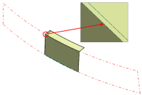
-
Check
No trim if you do not want the base surface to be modified.
-
Check
Trim to trim the base surface with the
mating flange.
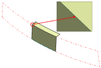
-
Check
Trim and Split to trim the base
surface with the mating flange and create an additional feature
that corresponds to the base surface split by the reference
element.
The Split feature is aggregated under the Mating Flange feature.
-
Click
Reverse Direction to inverse the thickness direction,
according to the orientation of the reference element.
As as consequence, the mating shape is displayed on the other side
of the base surface.
-
Click
Flip Flange to inverse the mating flange direction, according
to its orientation.
As as consequence, the mating shape is displayed on the other side
of the reference location.
-
Check
Both sides to create a both-side
mating flange using a second reference element.
By default, the Reference element, as well as the second
Reference direction, are the same as the first reference
element and direction, but you can choose other ones.
Similarly to the first
Reference direction, contextual menu items (Default
Selection and Clear Selection) are available for
the second
Reference direction.
 |
 |
| With the same reference element |
With a second reference element |
| |
|
| The second reference location is aggregated
under the Mating Flange feature and can be used as an input for
a further operation. |
 |
|
|
This option is
available with Trim and Split, providing the
reference elements are different. In this case, the portion
between the two elements is kept. |
|
|
Flip Flange
is grayed out when Both sides is activated. |
-
Check Linked directions
to link the second reference direction to the first one. Both
directions are the same, the second Reference direction field is
grayed out and filled with the same value as the first Reference
direction field.
|
|
This option is automatically checked if
Both sides is checked. If Both sides is unchecked, it is grayed
out. |
-
Check
Deviation to specify an individual deviation value.
This can be needed, for example, if unwanted tiny edges are created
because the default deviation tolerance is too small. In these
cases, you can increase the deviation value until the tiny edges are
removed.
By default, the deviation tolerance set in the
Maximum Deviation box in
Tools >
tab is used. Also,
the default deviation value used depends on the design range
settings.
|
Tiny Edge Created with
a Swept Surface as Input Element |
Tiny
Edge Removed by Increasing Deviation |
 |
 |
|
|