|
This command is only available with the Generative Shape
Optimizer product. |
 |
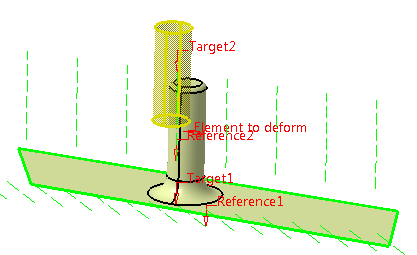
This task shows how to deform elements
based on shape morphing, that is matching each reference curve or
point (reference elements) onto a target curve or point (target
elements)
The deformation is then defined by the transformation of the
reference curves or points into target curves or points.
The elements used for the deformation do not necessarily lie on the
initial element. |
| |
Several cases are presented here, from the simplest one to cases
using various options. Note that whatever information is given in the
first example also applies to the following examples.
|
 |
Open the
ShapeMorphing1.CATPart
document. |
| |
Basic shape morphing deformation
|
| |
-
Click Shape Morphing
 . .
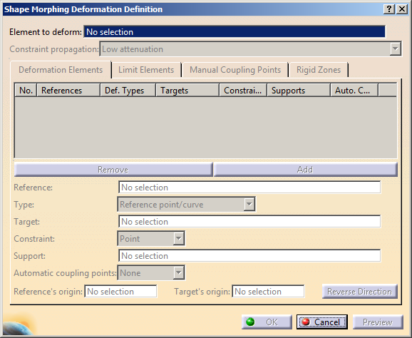
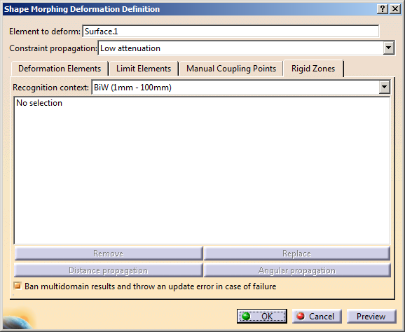
| The Shape Morphing Deformation Definition dialog box is
displayed. |
 |
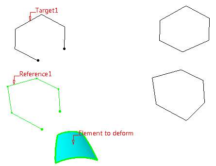
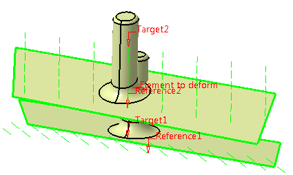
-
Select a curve in the 3D area and the selection
automatically appears in the Element to deform
box.
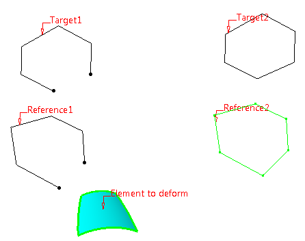
-
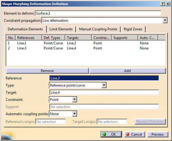
In the 3D area, successively select the first reference
element and the first target element.
-
Repeat this operation by selecting the second reference
element then the second target element.
 |
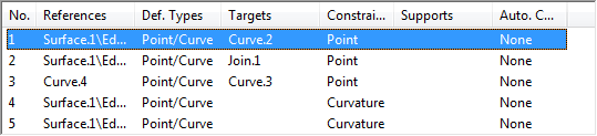
| As you select pairs of reference/target elements, the list in
the Deformation Elements tab is updated accordingly. |
 |
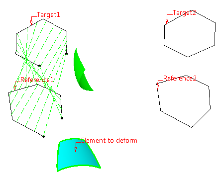
-
Click Preview to visualize the deformation.
The previsualization shows that:
- the deformation is applied to a group of points.
- there is a constraints' mapping between the reference and the
target curves.
|
 |
| You can visualize the mapping constraint by selecting a number
in the Constraint dialog box. |
-
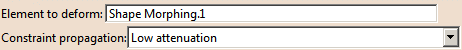
Click OK to create the deformed element.
| The element (identified as Shape Morphing.xxx) is added to the
specification tree. |
 |
You can apply a constraint on the target element with the
associated support element.
The combo list displays the available continuity types depending on
the reference/target elements you chose. |
-
If you select a reference
and a target element, the Point and the
Tangent continuity are available.
In the case of Point continuity, the
Support
field is grayed.
In the case of
Tangent continuity, select a support element so that the
continuity is kept.
-
If you select only
reference elements, all continuities
(Point, Tangent, and Curvature)
are available.
In the case of Tangent or Curvature
continuity, you do not need to select a support element as the
element to deform is taken into account.
-
If
you select the
Type as Reference translation /
Reference isometry / Reference similarity /
Reference linear transformation, the None
(G0), Rigid tangency and Rigid space
constraints are available.
|
|
 |
Deform an Element using Autocoupling
modes
|
|
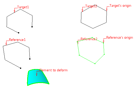
In case of reference and target wires consisting of many edges, you can
set coupling points automatically by selecting an autocoupling mode for
the reference-target pair selected in the Deformation Elements
tab.
- In the work area, select a surface as Element to
deform.
- Successively select the first Reference element and the
first Target element, which appears in the Deformation
Elements tab.
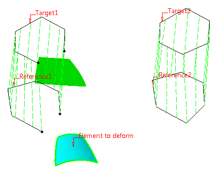
- Select Tangency in the Automatic
coupling points combo box.
|
All vertices located at G1 continuity breaks
places are selected to be set as coupling points.
This mode has only effect if
- the deformation wires have G1
discontinuities,
- reference and target have the same
number of G1 discontinuities.
|
If these conditions are not met, Tangency
autocoupling mode has no effect or, if
Vertices mode is also disabled, is not
available.
|
- Select a second reference and target element.
- Select Vertices in the Automatic
coupling points combo box.
All manually selectable vertices are selected to
be set as coupling points.
This mode is only available if
- the deformation wires have
selectable vertices.
- reference and target have the same
number of vertices.
|
If Vertices coupling mode is not
available, Tangency mode is also
disabled.
|
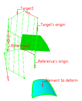
- Select a vertex from the second reference as
Reference's origin and a vertex from the second target
as Target's origin.
In case of closed wires, the deformation wires'
origins from where the definition of the pairs of
coupling points will start, has to be selected
manually.
In case of open wires, their start point is
automatically selected as origin.
|
- Click Preview to visualize the deformation.
- Select the first deformation elements line in the
Deformation Elements tab.
In the work area, the elements selected as first
reference and target are highlighted and handles
appear at the vertices.
In the Shape Morphing Deformation Definition
dialog box, the Reverse direction button
is enabled. |
- Click a handle or the Reverse direction
button.
The direction is reversed.
In case of open reference and target wires the
direction determines the start point on the wires
from where the first pair of coupling points is
defined. Reverse direction reverses start
and end point of the wires and thus the direction of
the pairs of points definition.
In case of closed wires, Reverse direction
reverses the direction in which the pairs of
coupling points are defined beginning from the
selected origin. |
- Click again Preview to visualize the
deformation.
- Click again a handle or Reverse direction
button to undo the last step.
- Click OK to create the deformed element.
The element (identified as Shape
Morphing.xxx) is added to the tree.
 |
|
|
| |
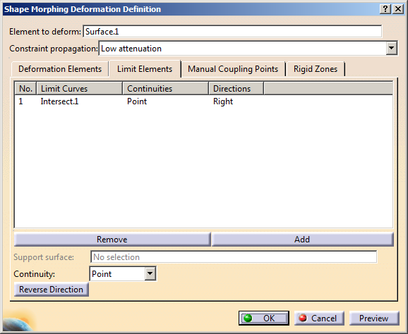
Defining Limit Elements
|
| |
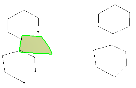
You can define one or
more limit elements to separate a feature in multiple parts. You can
then decide which parts of the feature you want to deform and which
parts to keep intact (freeze).
Here is an example using Intersect1. as Limit curve and a
Tangent
Continuity.
The Reverse Direction button enables to deform the element on
the other side of the limit curve. You can also click the arrow in the
3D geometry.
 |
By default, the limit element has a point continuity and right
direction. |
|
| |
|
| |
 |
| |
 |
| |
Coupling Points
|
| |
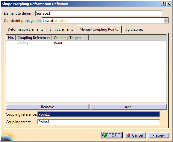
Use this tab to define coupling points in order to map reference
elements with target elements.
|
|
Points must be located on reference and target curves.
In the Coupling Points tab, select the
Reference point and its corresponding Target
point.
|
|
| |
-
In the Manual Coupling Points tab, select
the
Reference point and its corresponding Target point.
-
Click Add to select more coupling points or
Remove button to remove the coupling points.
|
| |
|
| |
|
|
-
You must always
select successively a reference then a target element to
define a pair. You cannot select all reference elements,
then all target elements for example.
-
When several pairs
of curves are selected, they must be ordered, not randomly
selected.
|
| |
|
 |
Reference and target curves can be multi-cells. Joined,
blended, or matched curves, for example, can be used as
reference or target curves. |
|
|
|
Rigid Zones
| Sometimes you need to preserve some faces, shapes and dimensions
without attenuating the deformation. |
|
 |
- Click Shape Morphing
.
The Shape Morphing Deformation
Definition dialog box is displayed.
|
- Select the surface as the Element to deform.
|
|
Rigid Zones functionality works only for
deforming surfaces. |
- Select the reference and target elements.
- In the Rigid Zones tab,
select the faces from the surface to deform by any of the following
ways:
- Select faces from the 3D area.
- Select faces previously extracted from the surface in
the tree.
- Select faces by creating extract features (Create
Extract, Create Extract(in point), Create Extract(in
tangency), Create Multiple Extract) by right-clicking the 3D
area or the list in the Rigid Zones tab.
|
|
|
You can remove and replace elements in the rigid
zones list by selecting the rigid zone from the list and
clicking Remove
or Replace.
|
|
- Optional: Select elements from the list and click
Distance Propagation to add to the list all the faces that
can be reached from the selected zone according to point continuity
propagation.
| Note: Depending on the part size and complexity, this action
may take appropriate time. |
- Optional: Select elements from the list and click
Angular Propagation to add to the list all the faces that can
be reached from the selected zone according to tangent continuity
propagation.
| Note: Depending on the part size and complexity, this action
may take appropriate time. |
- Optional: Click Preview to see the preview of
the deformed surface.
In the following examples you can see the preview of the
deformed surface when rigid zones are not selected, when rigid
zones are selected and when rigid zones are removed.
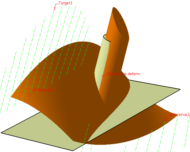
When no rigid zones are set the preview appears in
orange color.
|
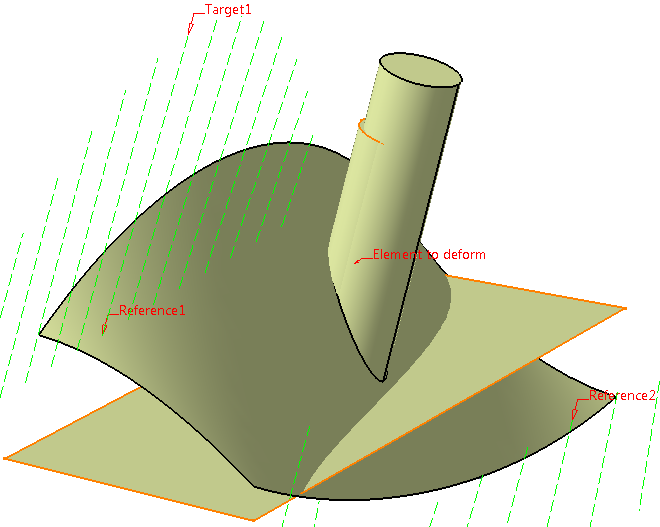
When rigid zones are set the feature is updated and no
orange preview appears. |
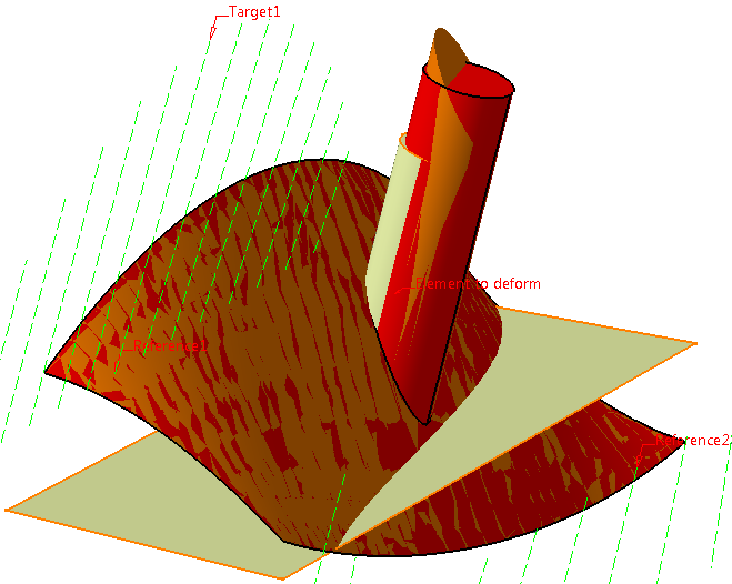
When all the rigid zones are removed, the previously
computed result is seen in red color and the new result
in orange color. |
|
|
|
- In the Recognition context combo list, change the
industry to Power Train.
If faces set as rigid zones share fillets or chamfers with
the surface to deform, in most cases the geometry is too complex
to allow sewing the deformed surface to these rigid zones. In
this case, the Shape Morphing Feature's result is not connex (i.
e. it is multi-domain).
If the fillets or chamfers are constant, the Recognition
context combo list options allow sewing translated zones
sharing fillets or chamfers with the surface to deform to this
surface, provided the fillet's radius or chamfer's length
belongs to the recognition context's range.
The industries proposed have specific ranges, which are subject
to change, in particular Ship Building's one:
| Industry |
Fillets'
range |
Chamfers' range |
| Power Train |
0mm - 15mm |
0mm-15mm |
| BiW (Body in White) |
1mm - 100mm |
1mm-100mm |
| Consumer Goods |
0mm - 50mm |
0mm-50mm |
| Ship Building |
0mm - infinity |
0mm-infinity |
| High Tech |
0mm - 1.5mm |
0mm-1.5mm |
| Building |
1mm - 100mm |
1mm-100mm |
| Machine Design |
0mm - 15mm |
0.03mm-1.5mm; angles range: 30deg-60deg |
|
- Click Preview.
| The fillets' radius does not belong to Power Train's
radii range, therefore, an Update Error dialog box
opens. |
- Click OK to close the dialog box.
The translated zones which cannot be sewn to the deformed surface
because they share smooth edges with the surface to deform are displayed
in yellow.
- Change the recognition context to BiW.
- Click Preview again.
The fillets' radius belongs to BiW's radii range. The
surface is deformed and the rigid zones with shared smooth edges
translated. The fillet between them is set back.
 |
- Click OK to create the deformed surface.
The Multi-Result Management dialog box appears if
some rigid zones cannot be sewn to the deformed surface.
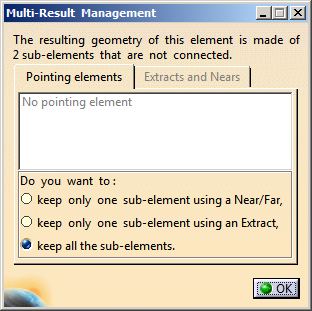 |
- Click OK.
| Note: Select keep all the sub-elements option to
create Extract Features of the deformed surface and translated
zones that could not be sewn to the deformed surface. |
|
| |
Use the Parameters Capability
|
| |
Use the Constraint propagation list to define the constraint
propagation on the deformed surface to obtain the desired shape.
|
| |
In the Constraint propagation list, select the desired
constraint propagation type. The different constraint propagation are:
- Low attenuation
- Medium attenuation
- Strong attenuation
- Very strong attenuation.
|
|
- The Strong attenuation and Very strong
attenuation constraint propagations cannot maintain
the
Reference linear transformation continuity.
- The magnitude of the deformation gets lower when the
value of the constraint propagation is higher and thus large
deformations are possible even with the Medium
attenuation and Low attenuation
options.
|
|
| |
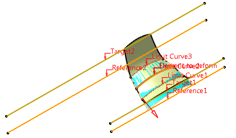
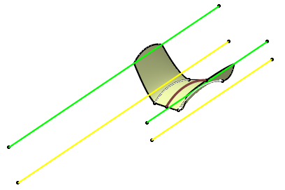
Deform a Surface with Limit Elements
|
| |
Sometimes, you need to create a deformed element in relation to
another element. The shape morphing capability lets you fix an element
that can be used by another one, thus allowing you to retain a
connection between elements while deforming the initial element. |
|
|
-
Click Shape Morphing
.
| The Shape Morphing Deformation Definition dialog box is
displayed. |
-
Select the surface or the curve as the Element to
deform.
-
Select the first reference element.
-
Select the target element.
-
Click Add to add another reference element.
-
Successively select the second reference element then
the target element.
-
Click OK to create the deformed element.
|
| |
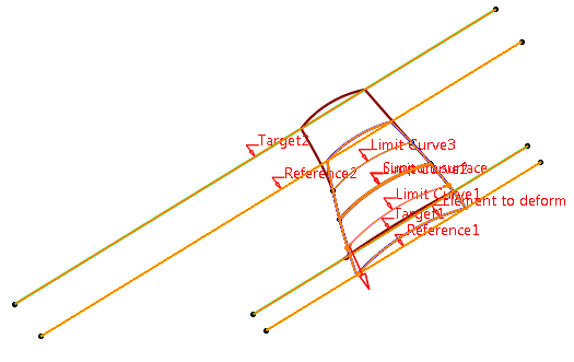
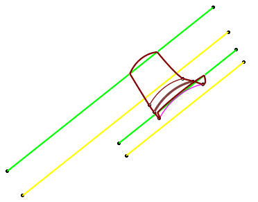
Deform a Wireframe with Limit Elements
|
| |
You can deform a wireframe with limit elements, provided they all lie on
the wireframe’s support surface. |
|
|
-
Click Shape Morphing
.
| The Shape Morphing Deformation Definition dialog box is
displayed. |
-
Select the wireframe as the Element to deform.
-
Select the first reference element.
-
Select the target element.
-
Click Add to add another reference element.
-
Successively select the second reference element then
the target element.
-
Click the Limit Elements tab.
-
Select one or more limit elements and adjust their
continuity and direction as per requirement. Refer Define Limit
Elements.
|
|
All the limit elements should lie on the support surface
that contains the wireframe. |
-
In the Support surface box, select the support surface.
|
|
The Support Surface box is available only if you select
a wireframe for deformation. |
-
Click OK to create the deformed element.
|
| |
Diagnosis
|
| |
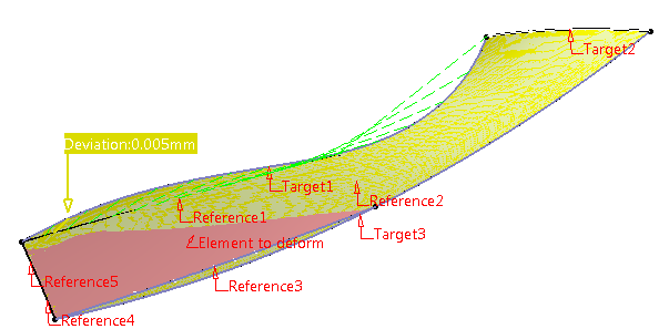
This capability lets you visualize the deviations in the 3D geometry
when the result is not fully accurate.
The Warnings dialog box may also be displayed. Refer to the
Managing
Warnings chapter for further information. |
|
|
-
Click Shape Morphing
.
| The Shape Morphing Deformation Definition dialog box is
displayed. |
-
Select the surface or the curve as the Element to
deform.
-
Select the references, target elements, and
Constraints.
-
Click Preview to visualize the deviations:
 |
| The Warnings dialog is also displayed. Refer to
Managing Warnings for further information. |
-
Select a line in the dialog box to display the
corresponding mapping and deviation.
 |
Here are the cases where warnings are displayed.
- When inputs are of bad quality:
|
|
To solve the above
warnings, we advise you to :
-
Use the
Curve
Smooth command to smooth the small discontinuities, then
-
Use the
coupling point tab to associate the great
tangency or curvature discontinuities between target and
reference.
|
- When reference curves intersect, there may be an
incompatibility between constraints:
- If the targets do not intersect
- If the targets intersect but the mapping between reference
and targets do not associate the reference's
intersection with the targets'
intersection. In this case, we advise you to add coupling
points.
- If the tangency constraint cannot be guaranteed.
|
|
|
|
In the Knowledge Base
About selecting rigid zones |
| |
 |