 |
This command is only available with the
Generative Shape Optimizer or Automotive Body in White Templates product. |
 |
This task shows how to include a seat surface
onto a base surface. |
 |
Open the Diabolo1.CATPart document. |
 |
-
Click Diabolo
 in the BiW Templates toolbar.
| The Diabolo Definition dialog box is displayed. |
-
Select the Seat Surface.
 |
The seat surface must have a
closed contour and belong to one domain. |
-
Select the Base Element.
 |
If the Base Element selected is a plane it is
considered as a
creation feature, while if it is a
surface, it is considered as a modification feature. |
 |
When you click OK, the reversal of Base Element from
plane to surface or vice versa is not allowed. |
-
Optional: In the Faces to Modify
box, select one or multiple faces to split the base surface and to
determine an intermediate base surface.
 |
- The faces should lie on the base surface and should be
connected to each other so that they form a single domain when
joined together.
- When joined together, the boundary should be able to cut the
base surface into two parts.
- If the faces overlap with other faces of the base element
after extrapolation, you will
get a warning message.
|
-
Select the Draft Direction.
| To define this direction, you can select either a plane, a line
or an axis X, Y, Z. |
| The draft direction is not mandatory: the default direction is
the normal direction to the seat surface. |
-
Select the Draft Angle.
There are three ways to define the draft
angle under the following tabs:
- Wholly
defined: the draft angle is applied to all the edges of
the seat surface boundary.
In addition, you can also specify the
angle by clicking Law. This law is applied along the seat
surface boundary.
The Law type that can be specified is Constant or
Advanced.
- G1-Constant:
separate draft angles are applied to each set of edges continuous in
tangency.
- Location
values:
the draft angle is specified at different vertices along the
seat surface boundary. The seat boundary should be continuous in
tangency.
|
| The default draft angle value is five degrees. |
-
Click Preview.
-
Click Reverse
Direction to invert
the orientation of diabolo.
 |
- The Reverse
Direction button is
enabled only if there are multiple solutions possible to create
the diabolo. If there is only one solution possible, this
button is disabled.
- You can also click the red arrow in the geometry to
change the orientation.
|
-
Click Preview again.
-
Click OK.
| The diabolo (identified as Diabolo.xxx) is added to
the specification tree. |
 |
 |
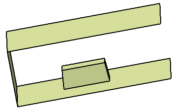
| Diabolo with a 5 degrees as draft angle |
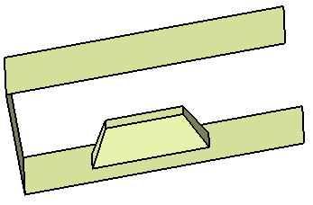
Diabolo with a 30 degrees as draft angle |
| |
|
|
|
|
Diabolo on Volume
|
 |
You can now create a diabolo with a volume or a solid feature as the
Base Element.
Here is an example with a volume. |
|
 |
Open the Diabolo2.CATPart
document. |
 |
-
Click Diabolo
 in the BiW Templates toolbar.
| The Diabolo Definition dialog box appears. |
-
Select the Seat Surface.
 |
-
The seat surface must
have only one boundary and belong to one domain.
-
The seat surface should
not completely cross the base element, otherwise an error message
is issued.
|
-
Set the volume as the Base Element.
-
Click Reverse Direction to invert
the orientation of diabolo.
 |
This button is
enabled only if there are multiple solutions possible to create
the diabolo. If there were only one solution possible, this
button is disabled. |
-
Click OK to create the diabolo on volume.
|
|
 |
![]()