- Reads and decodes geometric dimensions and tolerances applied on CAD data.
- Accurately evaluates actual size, position and form of the mesh for each selected tolerance.
- Provides you with:
- An OK/KO status for each tolerance in the dialog box.
- A color map in the 3D viewer.
- A defect analysis tool via a slider in the dialog box (whenever meaningful for the current tolerance).
- Summarizes the results in a report.
- Only the following geometric dimensions and tolerances are supported in this release:
Tolerance Type Tolerance Name Applying to form flatness so called planar surface form cylindricity so called cylindrical surface form circularity so called cylindrical or conical surface form straightness cylinder axis form straightness cylindrical generatrix form surface profile surface orientation parallelism surface/reference plane orientation perpendicularity surface/reference plane orientation angularity surface/reference plane dimension linear so called planar surface dimension angular so called planar surface dimension linear cylinder diameter dimension linear cylinder/cylinder distance (interaxial) orientation perpendicularity cylinder/plane position coaxiality cylinder/cylinder - Reference planes are currently computed as least squares planes. True reference planes computation based on infinite norm are not yet supported.
- Semantic dimensions are not currently supported. This applies in particular to linear dimensions.
The mesh must be properly aligned with the corresponding exact CAD data (by best fit for example).
In order to be properly analyzed, the mesh must be segmented into different areas. An automatic segmentation is provided inside the command, but you can use any other segmentation tool as well (before entering the command):
- If the input is an already segmented mesh, the command takes this segmentation into account. No automatic segmentation is started. This way, you have full control over the segmentation used within the command.
- If input is a non-segmented mesh (a mesh with just one internal cell), the automatic segmentation is started (this segmentation is guided by the aligned exact geometry, hence the requirement of a proper alignment).
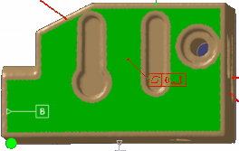
Open the GeometricTolerancesChecker01.CATPart from the samples directory.
-
Click Geometric Tolerances Checker
 in the Check Deviation toolbar.
The dialog box is displayed.
-
Select the tolerances you want to check:
- Either pick them directly.
- or pick the CAD surfaces related to them in the 3D viewer (In this case, the tolerances are deduced from the surfaces.)
-
Multi-selection
 is available.
The supported tolerances are listed with their requested tolerance values:
-
Optional: Select the Radius check box: when the cloud of points is noisy, it is difficult to have the boundaries of the CAD surface going through all the points.
When you select this check box, the points inside a circular pipe centered on the surface edge are not taken into account. You can set the value of this radius.
This option being useless for already segmented input meshes, it is available for non segmented meshes only (grayed otherwise). -
Click Apply to start the inspection.
-
Each tolerance is evaluated and the measured value is displayed, with an OK/KO status:
-
The tolerances in the 3D viewer are colored according to their status.
-
-
Select the Perpendicularity.1 line.
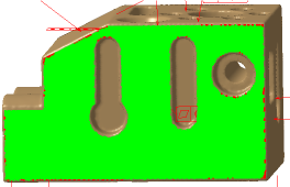
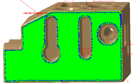
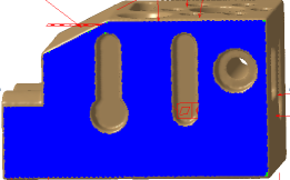
The defect is highlighted in the 3D viewer, with a color map:- Areas in green meet the tolerance.
- Areas in Red are above the tolerance.
- Areas in Blue are below the tolerance.
The slider at the bottom of the dialog box becomes available, depending on the tolerance selected.
-
Move this slider. The distribution of colors changes in the defect map.
Some tolerances are evaluated from a reference named datum. Depending on the type of the tolerance, this reference may slightly move around its default position. This is the “clearance” of the reference.
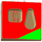
The slider in the dialog box lets you move the reference from one extremity to the other, as follows:- First example:
- First extremity of the reference
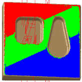
- Intermediate position of the reference
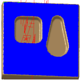
- Second extremity of the reference
Obviously, this face is globally flat and the parallelism criterion is reached, apart along its edges. The KO diagnosis is due to the welds between the planar faces. If you select the Radius check box and increase this value, the visualization turns into
confirming that, at a certain distance from its edges, the face is flat, the parallelism criterion is reached. - First extremity of the reference
- Second example:
- First extremity of the reference
- Intermediate position of the reference
- Second extremity of the reference
Whatever the position of the reference, it is not possible to reach the parallelism criterion of this geometric tolerance. This is a true defect to be solved on the physical part.
- First extremity of the reference
- First example:
-
Click OK to validate and exit the command.
The inspection display is erased from the screen.
A feature GD&T Check.x is created in the specification tree under the Deviation Check node.
-
Either add the GD&T Check.x feature as a More Elements to Export in a Deviation Report:
- Click Deviation Report
 in the Check Deviation toolbar.
 - Go to the Deviation tab and to More
Elements to Export.
- Click Add and select the GD&T Check.x you have created (you can select several GD&T Check.x features).
- The exported report looks like this:
Each GD&T Check.x feature has its own section in the Deviation check results web page, and can be accessed directly from the navigation panel.
- Click Deviation Report
-
Or capture the image of the GD&T Check.x feature to insert it in the deviation report.
- Double-click the GD&T Check.x feature to display it.
- Create the image with the Tools > Images > Capture menu or by any other means.
- Click Deviation Report
in the Check Deviation toolbar.
- Go to the Insert Images tab and click Add.
Select the image to insert.
- The exported report looks like this:
![]()