The Automatic Surface command is adapted to many types of shapes.
- It can create complex surfaces with a minimum set of Nurbs.
- It can take holes into account.
- It preserves fillet with small radius (but not very sharp edges).
The input required is a mesh (not a cloud of points):
- It may not have non-manifold vertices or triangles.
- It must be a mono-cell mesh, without non-connex zones.
The output is a V5 feature. It is automatically updated if the input is modified.
This task shows you how to:
Set the Options
-
Click Automatic Surface
 and select Sample as the
Mesh.
and select Sample as the
Mesh.
The name of the mesh you have selected is displayed in the dialog box.
The is now available and enables you to hide or show the mesh.
By default, the check boxes Free edge tolerance, Full internal tangency, and Regular stream lines are selected.
The parameters values can be edited and the check boxes can be cleared or selected according to your needs. -
Key in the Mean surface deviation,
i.e. the average deviation between the surface that will be created and the input mesh,
computed on all mesh vertices.
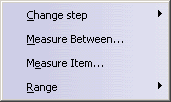
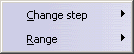
A contextual menu is available.
-
Key in a Surface detail value: The higher the value, the higher the respect of details.
A contextual menu is available.
-
Optional: if full internal tangency is not required, clear this check box.

The output will be smaller in term of memory size and control points.
However, you will not be able to recover full internal tangency later on, e.g.
with healing or filleting commands. Nor will you be able to perform thickness or offset operations on the output surface. -
Decide if you want:
-
Regular stream lines:
-
Or not:
-
Regular stream lines:
-
Click Preview to preview the surface.
-
Click More to have access to statistics and some display check boxes:
The Statistics are:
- Output faces:
global count of faces contained in the output surface, - Max surface deviation:
value of the maximum deviation between the surface and the mesh,
also displayed with the spikes, - Max free edges deviation:
value of the maximum deviation between the free edges and the mesh,
also displayed with the spikes, - Mean surface deviation:
value of the mean deviation between the surface and the mesh, - xx% of yyy points Ok:
percentage of the measured points that are under the Mean surface deviation.
- Output faces:
-
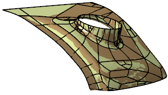
Select the Spikes check box to visualize the deviations between the mesh and the surface:
The points with the maximum deviation on the surface or
on free edges are displayed on a small yellow rectangle,
with the corresponding value of the deviation.- Deviation enables you to display only the spikes on
points
with a deviation greater than this value. - Negative and positive deviations are displayed in different colors.
- Deviation enables you to display only the spikes on
points
-
Click
 to visualize the deviations on the surface:
-
Click
 to visualize the deviations on the free edges
(only available when free edges exist):
Should you require more accurate deviation results, go to Deviation Analysis to perform this analysis once the automatic surface has been generated.
-
Click OK.
A feature Automatic Surface.x is created.
-
Right-click the AutomaticSurface.x feature in the specification tree and select Convert Into Subdivision in the contextual menu.
An Imagine & Shape Subdivision Surface.x feature is created.

Convert Into Subdivision is not available if the Automatic Surface.x has been created with Regular stream lines without Extend surface.
Create Surfaces with Regular Stream Lines
You can request Regular Stream Lines. This is the option by default.
- Stream lines in the output are regular and smooth.
- The Free edge tolerance check box is always selected and taken into account but is not editable.
- The check boxes Fill holes and Extend surface are available.
|
|
Regular Stream Lines, Fill holes and Extend surface are not available for closed meshes. |
-
Optional: Select the Fill holes check box.
- Fill Holes is not selected:
- Fill Holes is selected:
- Fill Holes is not selected:
-
Optional: Select the Extend surface check box and adjust the extension with the slider.
By default, Extend surface is not selected, the output surface is trimmed on the external and internal free edges of the mesh. - Extend surface is not selected:
- Extend surface is selected:
- Extend surface is not selected:
Create Surfaces with Any Stream Lines
You can clear the Regular Stream Lines check box.
- Stream lines in the output are less regular.
- The check boxes Fill holes and Extend surface are no longer available.
- The Free edge tolerance check box can be cleared, its value can be edited.
- Target ratio becomes editable.
-
Select or clear the Free edge tolerance check box i.e. the chordal value used to sample the mesh boundaries and to improve the quality of the surface with respect to the mesh boundaries.
- Free edge tolerance is not selected:
- Free edge tolerance is selected:
- Free edge tolerance is not selected:
-
Key in a Target ratio: This is the ratio of measured points with a surface deviation under the Mean surface deviation value. The actual ratio obtained may be different (greater or lower) than the one you have requested.
A contextual menu is available.
- A Target ratio next to 100 is time consuming.
- If the Mean surface deviation or the Target ratio requested cannot be reached, the surface is created and a message is displayed.
![]()